


68
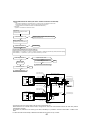
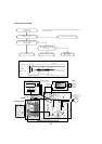
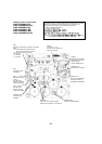
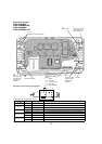
Outdoor power circuit board
PUMY-P36NHMU(-BS)
PUMY-P36NHMUR1(-BS)
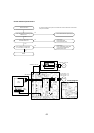
PUMY-P48NHMU(-BS)
PUMY-P48NHMU
1(-BS)
PUMY-P48NHMU
2(-BS)
PUMY-P48NHMUR3(-BS)
TABU/V/W
Connect to the compressor (MC)
Voltage among phases: 10V~180V AC
TABP1/SC-P1
Connect to 52C (P48NHMU)
Connect to ACTM (+)
(P36NHMU, P48NHMU2)
TABP2/SC-P2
Connect to the
ACTM(P)
CN4
Connect to the
outdoor controller
circuit board (CN4)
CN2
Connect to the outdoor controller circuit board
(CN2)
1-5:Transmitting signal to the outdoor
controller circuit board (0~5V DC)
2-5:Zero cross signal (0~5V DC)
3-4:18V DC
6-5:16V DC
7-5:16V DC
CN3
Thermistor (TH8)
<Heatsink>
CN5
Detection of primary
current
Connect to the
outdoor noise filter
circuit board (CN5)
CNDC
310V DC (1+, 3–)
Connect to the outdoor con-
troller circuit board
TABS/T
Connect to the outdoor
noise filter circuit board
Voltage among
phases: 208/230V AC
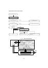
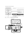
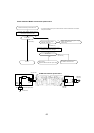
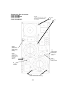
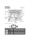
Brief Check of POWER MODULE
W Usually, they are in a state of being short-circuited if they are broken.
Measure the resistance in the following points (connectors, etc.).
If they are short-circuited, it means that they are broken.
1. Check of POWER MODULE
1.Check of DIODE circuit
S - P1 , T - P1 , S - N1 , T - N1
2.Check of IGBT circuit
P2 - U , P2 - V , P2 - W , N2 - U , N2 - V , N2 - W
Note:The marks, L , N , N1 , N2 , P1 , P2 , U , V and W shown
in the diagram are not actually printed on the board.
TABN1/SC-N1
Connect to the ACTM(-)
TABN2/SC-N2
Connect to the ACTM (N2)