


805
FX3S/FX3G/FX3GC/FX3U/FX3UC Series
Programming Manual - Basic & Applied Instruction Edition
36 Interrupt Function and Pulse Catch Function
36.2 Common Items
31
FNC277-FNC279
Data
Transfer 3
32
FNC280-FNC289
High-Speed
Processing 2
33
FNC290-FNC299
Extension File
Register Control
34
FNC300-FNC305
FX
3U
-CF-ADP
35
SFC•STL
Programming
36
Interrupt
Function
37
Special Device
38
Error Code
A
Version Up
Information
B
Execution Times
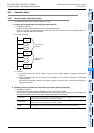
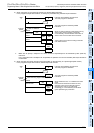
3. Operation when a timer is used [interrupt function]
Make sure that counting using a general timer is disabled, even a 1ms retentive type timer.
In an interrupt routine, use timers for subroutine program T192 to T199.
FX
3S PLCs are not equipped with timers for subroutine program.
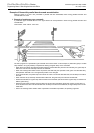
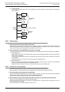
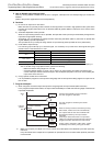
4. Non-overlap of input [input interrupt (with/without delay function) and pulse catch function]
The inputs X000 to X007 can be used for high-speed counters, input interrupts, pulse catch, SPD, ZRN, DSZR and
DVIT instructions and for general-purpose inputs.
Make sure inputs do not overlap with each other.
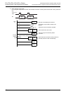
When using SFC program (STL instruction), do not drive state relays S in a SET or OUT instruction in an interrupt
program.
5. When using SFC program (STL instruction)
When using SFC programs (STL instruction), do not drive state relays S using SET or OUT instructions in an interrupt
program.
6. Operation of devices latched in the ON status [interrupt function]
Devices which were set to ON in an interrupt routine are held in the ON status even after the interrupt routine is
finished.
When the RST instruction for a timer or counter is executed, the reset status of the timer or counter is also held.
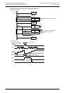
To turn OFF a device held in the ON status or for canceling such a timer or counter held in the reset status, reset such
a device or deactivate the RST instruction respectively inside or outside the routine.
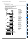
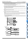
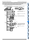
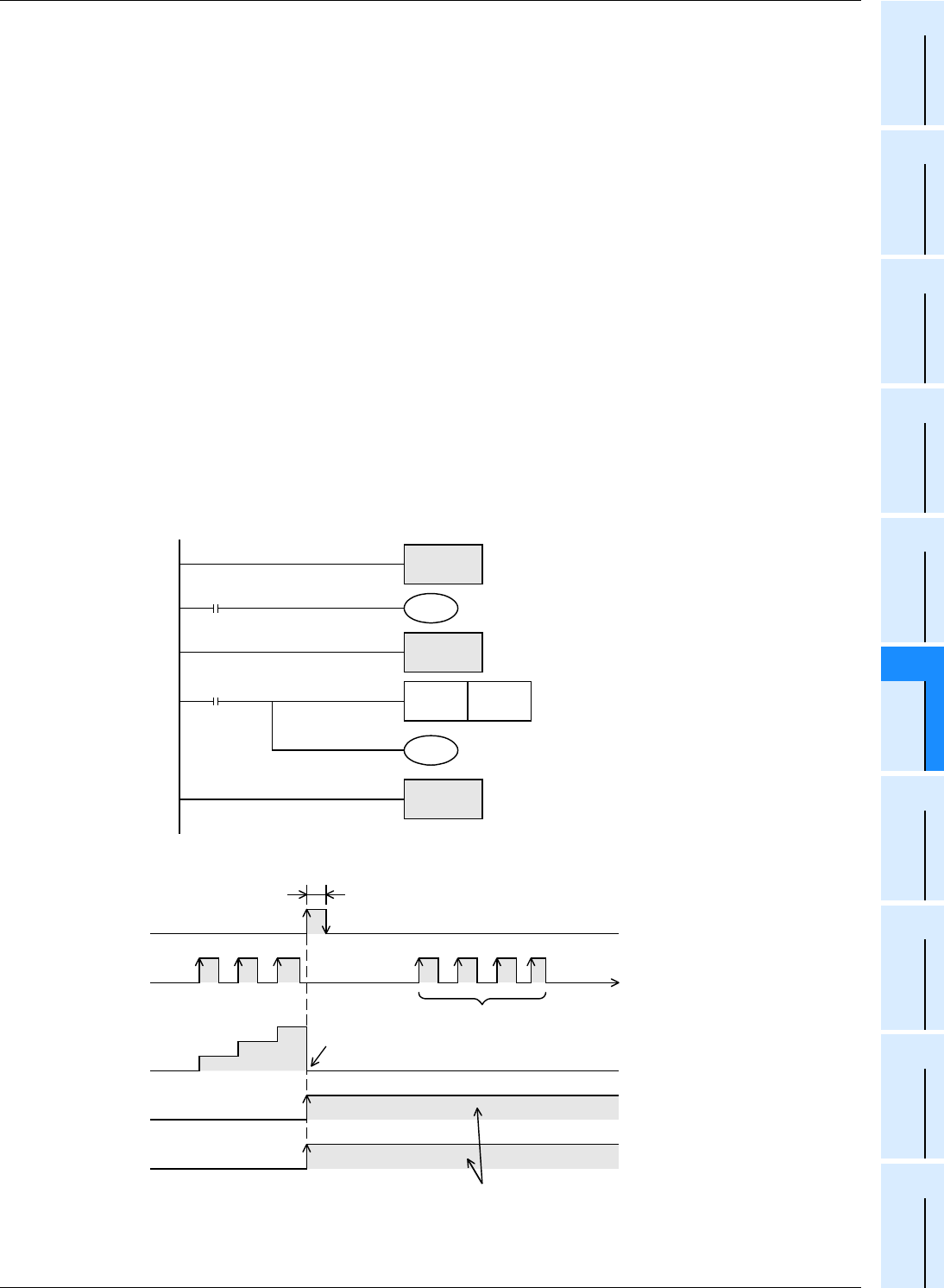
Example in which outputs are latched
In the program example shown below, the counter C0 is provided to count X001. When X001 turns from OFF to
ON, the interrupt program I001 is executed only in one scan, and then the counter C0 is reset and Y007 is output.
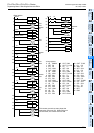
1) Program example
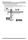
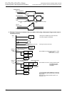
2) Timing chart
M8000
K10
FNC 04
EI
C0
RST C0
X001
FNC 06
FEND
FNC 05
IRET
I001
Y007
Step 0
Execution of interrupt
program I001 triggered
by X000
X001
Current
value of C0
1
2
3
Counter is
reset
Because the C0 reset
instruction is valid, the current
value of C0 remains unchanged
even if a pulses are input.
C0 remains reset
Y007 is being output
Outputs are latched.
RST
C0
Y007
Interrupt program