175
FX3S/FX3G/FX3GC/FX3U/FX3UC Series
Programming Manual - Basic & Applied Instruction Edition
6 What to Understand before Programming
6.5 General Rules for Applied Instructions
1
Introduction
2
Overview
3
Instruction
List
4
Devices
in Detail
5
Specified the
Device &
Constant
6
Before
Programming
7
Basic
Instruction
8
FNC00-FNC09
Program Flow
9
FNC10-FNC19
Move & Compare
10
FNC20-FNC29
Arith. & Logic
Operation
Instruction form and operation type
Applied instructions are classified into "16-bit type" or "32-bit type" by the size of handled numeric values. And by the
operation type, applied instructions are classified into "continuous operation type" or "pulse operation type".
Some applied instructions have every combination of this form and type, and others do not.
1. 16-bit type and 32-bit type
- Applied instructions handling numeric values are classified into the 16-bit type or the 32-bit type by the bit length
of the numeric value data.
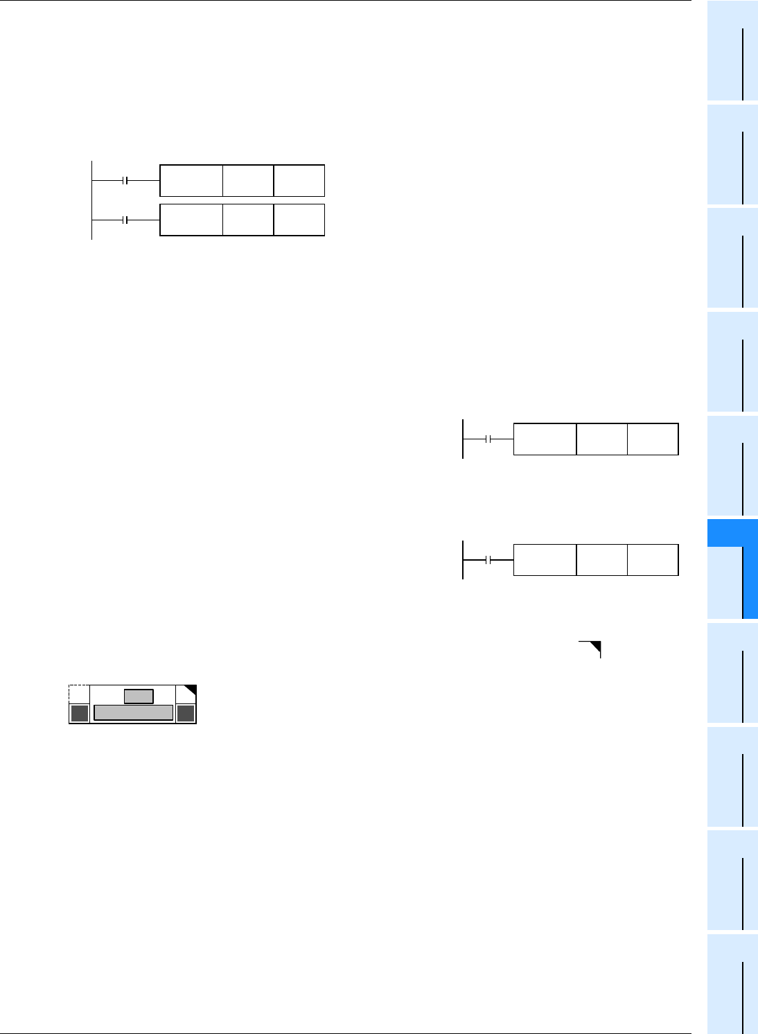
This instruction transfers the contents of D10 to D12.
This instruction transfers the contents of D21 and D20 to D23
and D22.
- In a 32-bit type instruction, the symbol "D" is added (example: DMOV).
- Either an odd or even device number can be specified, and a specified device is combined with a device having
the subsequent larger number (in the case of word devices such as T, C and D).
For avoiding confusion, it is recommended to specify an even device number (which will be the low-order side)
for an operand in a 32-bit instruction.
- 32-bit counter (C200 to C255) is regarded as 32 bits, and cannot be used as an operand in a 16-bit instruction.
2. Pulse operation type and continuous operation type
Pulse operation type
In the example shown in the figure on the right, when X000 turns from
OFF to ON , the instruction is executed only once, and is not executed
in any other case.
When it is not necessary to continually execute an instruction, use the
pulse operation type.
The symbol "P" indicates the pulse operation type.
"DMOVP" indicates also the pulse operation type.
Continuous operation type
The figure on the right shows a continuous operation type instruction.
While X001 is ON, the instruction is executed in every operation cycle.
In the continuous operation type of some instructions such as INC (FNC 24) and DEC (FNC 25), the contents of the
destination change in every operation cycle.
For applied instructions requiring attention in using the continuous operation type, the symbol " " is added to the
title of the explanation of such instructions as shown in the figure below.
In any case, instructions are not executed while the drive input X000 or X001 is OFF. And the destinations do not
change except when instructions specify otherwise.
Command 1
FNC 12
MOV
D10 D12
Command 2
FNC 12
DMOV
D20 D22
X000
FNC 12
MOVP
D10 D12
X001
FNC 12
MOV
D10 D12
P
FNC 12
MOV
No.
Instruction name
D


