779
FX3S/FX3G/FX3GC/FX3U/FX3UC Series
Programming Manual - Basic & Applied Instruction Edition
35 SFC Program and Step Ladder
35.1 SFC Program
31
FNC277-FNC279
Data
Transfer 3
32
FNC280-FNC289
High-Speed
Processing 2
33
FNC290-FNC299
Extension File
Register Control
34
FNC300-FNC305
FX
3U
-CF-ADP
35
SFC•STL
Programming
36
Interrupt
Function
37
Special Device
38
Error Code
A
Version Up
Information
B
Execution Times
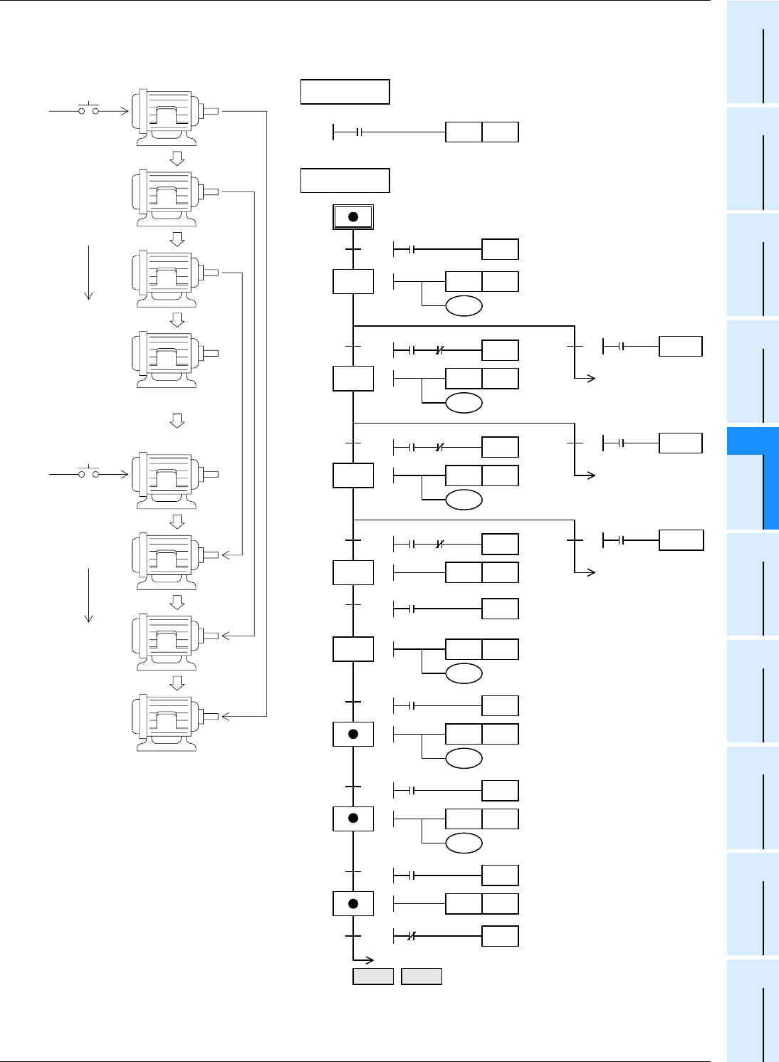
4. Example of sequential start and stop
The motors M1 to M4 are started in turn by a timer, and stopped in turn in the reverse order.
This SFC flow is based on a single flow, and has jumps of state relays.
This SFC program shows an example in which a part of the flow is skipped according to a condition, and the execution
is transferred to a state in a lower position.
The execution can be transferred to a state in an upper position.
20
M8002
0
1
Ladder block
SFC block
0
TRAN
X000
S0SET
T0
TRAN
T0
K20
Initial pulse
Start
Y000SET
Motor M1 is
started.
X001
21
T1
K30
Y001SET
Motor
M2 is
started.
27
TRAN
X001
Stop
9
2
TRAN
T1
X001
22
T2
K40
Y002SET
Motor
M3 is
started.
26
X001
Stop
10
TRAN
3
TRAN
T2
X001
23
Y003SET
Motor
M4 is
started.
25
X001
Stop
11
TRAN
24
T4
K40
Y003RST
Motor
M4 is
stopped.
4
TRAN
X001
5
TRAN
T4
25
T5
K30
Y002RST
Motor
M3 is
stopped.
6
TRAN
T5
26
T6
K20
Y001RST
Motor
M2 is
stopped.
7
TRAN
T6
27
Y000RST
Motor M1
is
stopped.
8
TRAN
Y000
0
RET END
M1
M2
M3
M4
M4
M3
M2
M1
2 seconds
3 seconds
4 seconds
4 seconds
3 seconds
2 seconds
X000
Start
X001
Stop
StartStop
In the case of stop in the middle of operation, the motors are stopped also in turn in the reverse order.


