


128
FX3S/FX3G/FX3GC/FX3U/FX3UC Series
Programming Manual - Basic & Applied Instruction Edition
4 Devices in Detail
4.8 High-Speed Counter [C] (FX3U/FX3UC PLC)
4.8.11 Cautions on use
• For a contact to drive the coil of a high-speed counter, use a contact which is normally ON during high-speed
counting.
• If the operation of a high-speed counter is triggered by a device such as a switch, the counter may malfunction due
to extra noise from switch chattering or contact bounce.
• The input filter of an input terminal for a high-speed counter in the main unit is automatically set to 5 µs (X000 to
X005) or 50 µs (X006 and X007).
Accordingly, it is not necessary to use the REFF instruction or special data register D8020 (input filter adjustment).
The input filter for input relays not being used for high-speed counters remains at 10 ms (initial value).
• The inputs X000 to X007 are used for high-speed counters, input interrupt, pulse catch, SPD/DSZR/DVIT/ZRN
instructions and general-purpose inputs. There should be no overlap between each input number.
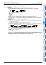
• When a counting pulse is not provided, none of the high-speed counter output contacts will turn ON, even if the
PLC executes an instruction where "present value = set value".
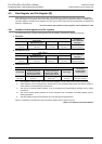
• Counting may be started or stopped for a high-speed counter when the output coil (OUT C***) is set to ON or OFF.
Program this output coil in the main routine. If the output coil is programmed in a step ladder (SFC) circuit,
subroutine or interrupt routine, counting cannot be started or stopped until the step ladder or routine is executed.
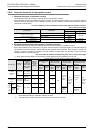
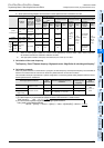
• Make sure that the signal speed for high-speed counters does not exceed the response frequency described
above. If an input signal exceeds the response frequency, a WDT error may occur, or communication functions
such as a parallel link may malfunction.
• The response frequency changes depending on number of used counters, but the input filter value is fixed to 5 µs
(X000 to X005) or 50 µs (X006 and X007).
Note that noise above the response frequency may be counted depending on the filter value of the used input.
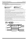
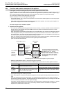
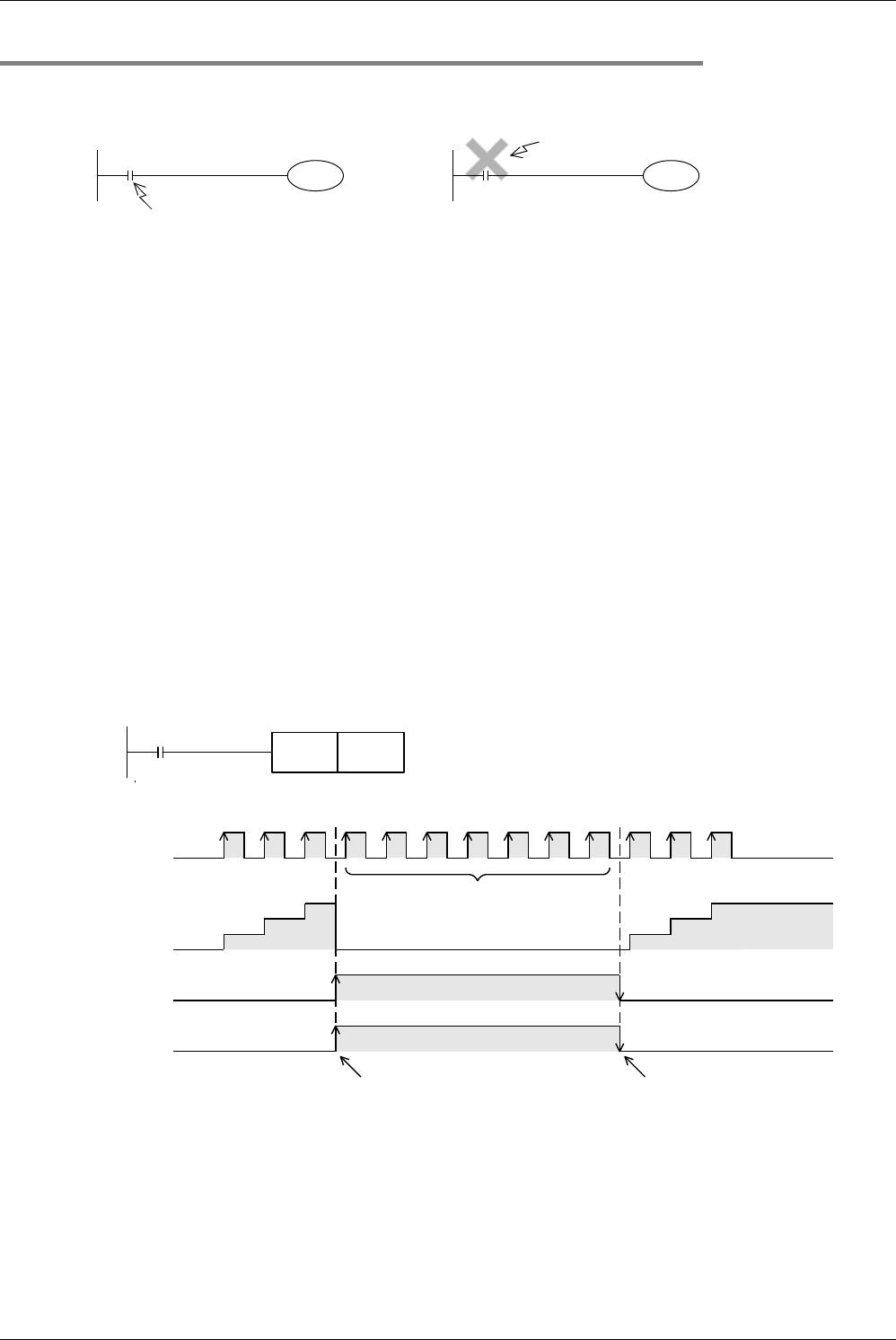
• When a high-speed counter is reset by the RST instruction, it cannot count until the RST instruction is set to OFF.
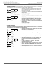
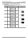
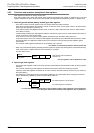
1) Program example
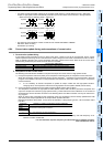
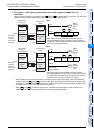
2) Timing chart
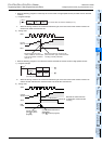
Example: M8000 (RUN monitor NO contact)
C235
X000
C235
Input number corresponding to
C235
Program a contact which is
normally ON during counting.
If a number of input relay for counting is specified,
high-speed counter cannot execute accurate counting.
X010
RST C235
C235 is reset while X010 turns ON.
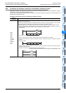
X010
RST C235
C235 is reset while X010 turns ON.
X000
Current
value of C235
1
2
3
The current value does not change
even if pulses are input because the
C235 reset instruction is valid.
C235 remains reset
"RST C235" is set to ON
because the contact turns ON.
X010
RST
C235
1
2
3
"RST C235" is set to OFF
because the contact turns OFF.