


SDC / DHC Technical data
EN2H-0221GE51 R0808 251
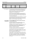
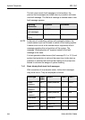
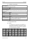
8.1.1 Installation recommendations
Mains voltage lines
(mains connection, burners, pumps, servo motors):
Diameter 1.5 mm
2
Max. permissible length No limit for installation in buildings.
Safety low-voltage lines
(sensors, ext. switches upon demand via switching contact, modem connection lines, analog
signal lines etc.)
Diameter 0.5 mm
2
Max. permissible length 100 m (looped circuit); longer connection lines should be avoided
to prevent the risk of interference
Data bus lines
Diameter 0.6 mm
2
Max. permissible length 50 m (looped circuit, longest distance between a central device
and a device to be supplied); longer connection lines should be
avoided to prevent the risk of interference.
Recommended layouts J-Y(St)Y 2 x 0.6
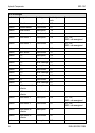
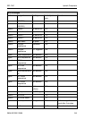
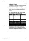
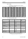
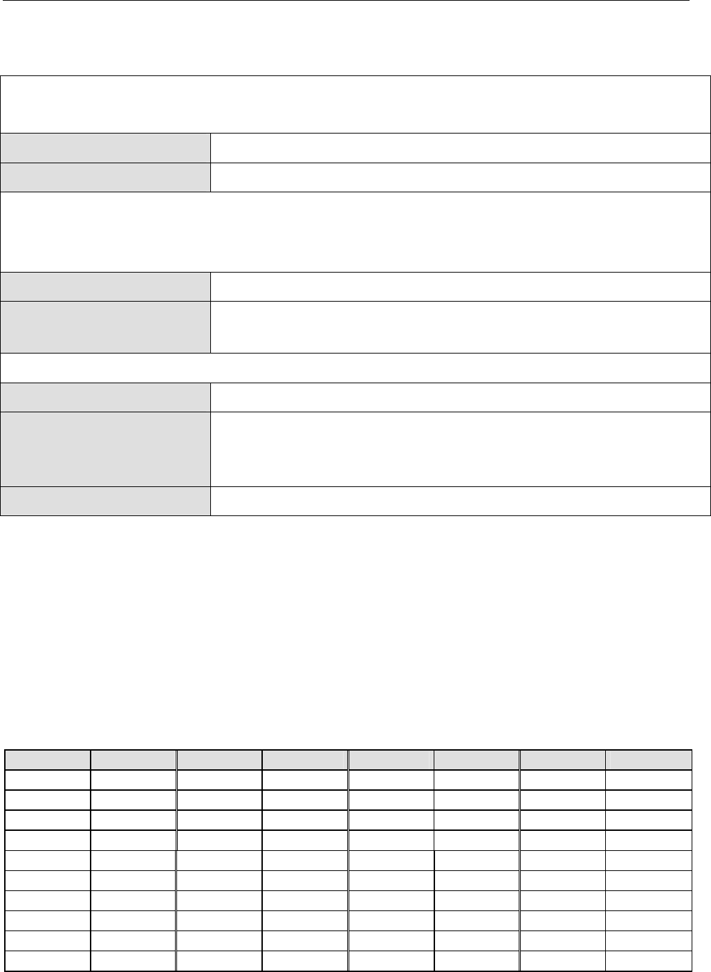
8.2 Sensor resistance values
8.2.1 NTC 20
For outside sensor (OT), heat generator sensor (BLRS/BS), tank
sensor (DHWS), mixed heating circuit 1 flow sensor (VF1), mixed
heating circuit 2 flow sensor (VF2), variable input 1 (VI-1) (setting
not for exhaust gas sensor), variable input 2 (VI-2), variable input 3
(VI-3), collector tank/buffer sensor (SBUS).
°C kΩ °C kΩ °C kΩ °C kΩ
–20 220.6 0 70.20 20 25.34 70 3.100
–18 195.4 2 63.04 25 20.00 75 2.587
–16 173.5 4 56.69 30 15.88 80 2.168
–14 154.2 6 51.05 35 12.69 85 1.824
–12 137.3 8 46.03 40 10.21 90 1.542
–10 122.4 10 41.56 45 8.258 95 1.308
–8 109.2 12 37.55 50 6.718 100 1.114
–6 97.56 14 33.97 55 5.495 – –
–4 87.30 16 30.77 60 4.518 – –
–2 78.23 18 27.90 65 3.734 – –