


CANopen DSP 402 Implementation Guide
MAN-CAN402IG (Ver. 1.2)
91
12.3 Functional Description
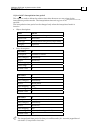
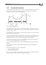
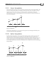
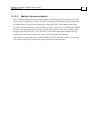
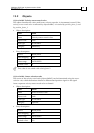
In Interpolated Position mode, the drive executes a time-synchronized motion path. The
user specifies the value of the reference signal at an initial time, and at fixed-time
intervals from then on (as in the following figure).
TimeT start
T∆ T∆ T∆ T∆
P0
P1
P2
P3
P4
Figure 9: Interpolated Motion
In the figure, the time interval
is set by the object 0x60c2, in milliseconds. The data
records P0,P1,P2,… (object 0x60C1) to define the motion path data relating to the times
T∆
,,2
start start start
TT T+∆ + ∆,...
The motion path is synchronized to the CAN microsecond timer, as set and corrected by
the SYNC-Time stamp mechanism.
The user must specify the data records P0,P1,P2,…fast enough – at an average rate of at
least one record per
T
∆
. The drive can store up to 64 records, so that the path may be
programmed in bursts in order to relax the feeding real-time requirements.
In order to enter IP mode, use the controlword (0x6040) to start the motor, and then use
the modes of operation(0x6060) object to select IP mode.
You can monitor the mode using the statusword (0x6041) and modes of operation display
(0x6061).
The interpolation sub-mode in object 0x60C0 determines the type of interpolation
performed.
The Elmo drive supports two types of interpolation:
Linear interpolation (default)
Cubic spline interpolation
The structure of the 0x60C1 object depends on the interpolation sub-modes. Refer to the
definition of 0x60C1 to learn more about sub-mode switching.