


Bit 4: Voltage Enabled:
High voltage is applied to the drive when this bit is set to 1.
Bit 5: Quick Stop:
When reset, this bit indicates that the drive is reacting to a Quick Stop request. Bits 0,
1 and 2 of the statusword must be set to 1 to indicate that the drive is capable of
regenerating. The setting of the other bits indicates the status of the drive (for
example, the drive is performing a quick stop in reaction to a non-fatal fault. The
fault bit is set in addition to bits 0, 1 and 2).
Bit 7: Warning:
A drive warning is present if bit 7 is set. While no error has occurred, this state must
still be indicated; for example, job refused. The status of the drive does not change.
The cause of this warning may be found by reading the fault code parameter. This
bit is set when an illegal controlword is received and reset after at least one statusword
of this transition has been transmitted.
Bit 8:
This bit is reserved for the manufacturer. It is not used and is set to 0.
Bit 9: Remote:
If bit 9 is set, parameters may be modified via the CAN network, and the drive
executes the contents of a command message. If the bit remote is reset, the drive is in
local mode and does not execute the command message. The drive may transmit
messages containing actual valid values such as a position actual value, depending on
the actual drive configuration. The drive accepts accesses via SDO in local mode.
The Remote bit is always set by the Elmo servo drive.
Bit 10: Target Reached:
Bit 10 is set by the drive to indicate that a set-point has been reached. The set-point is
dependent on the operating mode. The relevant description is found in the chapter
about the special mode. The change of a target value by software alters this bit.
If the quick stop option code is 5 or 6, this bit is set when the quick stop operation is
finished and the drive is halted.
If a Halt occurs and the drive has halted, this bit is also set.
Bit 11: Internal Limit Active:
The drive can set this bit to indicate that an internal limitation is active (such as
software position limit).
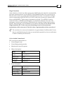
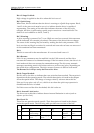
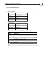
Bits 12 and 13:
These bits are operation-mode specific. Their description is found in the chapter
about the special mode. The following table provides an overview of the bits:
Operation Mode
Bit
vl pp pv tq hm ip
12 Reserved Set-point
acknowledge
Speed Reserved Homing
attained
ip mode
active
13 Reserved Following
error
Max slippage
error
Reserved Homing
error
Reserved
CANopen DSP 402 Implementation Guide
MAN-CAN402IG (Ver. 1.2)
30