


CANopen DSP 402 Implementation Guide
MAN-CAN402IG (Ver. 1.2)
19
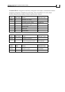
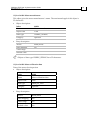
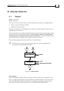
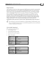
Data description:
31 22 21 16 15 4 3 2 1 0
Manufactu
rer specific
Digital
input 1…10
logic state
Reserved Interlock Home
switch
Positive
limit
switch
Negative
limit switch
MSB
The switch must be “active high.”
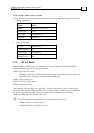
Notes:
The interlock is always 0.
“Active high” means that the bit is set to high when the switch is logically
active.
Bits 16 – 25 reflect the logic active state of the digital inputs, starting from 1.
Logic active means that the switch can be active in either high state or low state
according to the IL[N] definition. More information can be found in the
SimplIQ
Command Reference Manual.
Different SimplIQ drives support a different number of digital inputs. It is
advised to use only the relevant bits according to the specific drive.
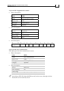
This object is evaluated every 3 milliseconds.
When mapped as asynchronous, this object is transmitted at every change within the
calculation resolution period. Inhibit time can be used to prevent busload or to control
the time latency causing the same TPDO to be transmitted due to other asynchronous
events.