


IB01602011E For more information visit: www.Eaton.com
Instructional Booklet
Effective: March 2007 Page 7
Fixed and Drawout Magnum Transfer Switches
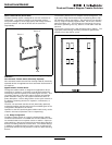
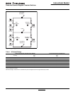
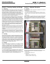
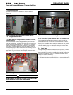
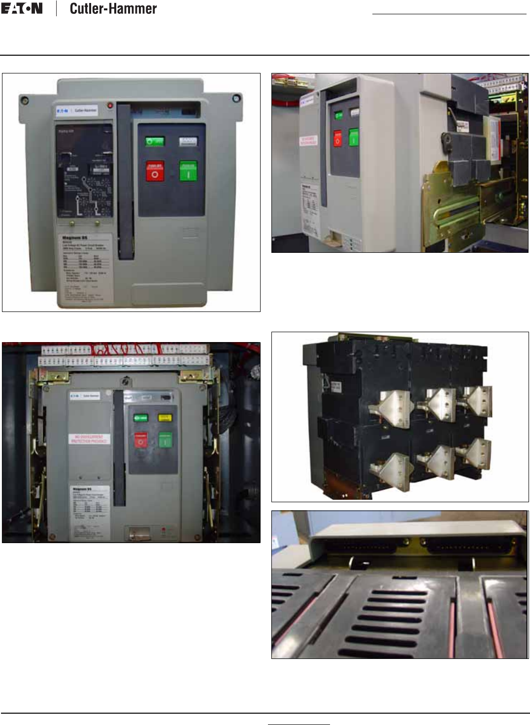
Figure 7. Fixed Switching Device for the Magnum Transfer
Switch.
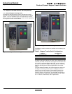
Figure 8. Drawout Switching Device Installed in the Magnum
Transfer Switch.
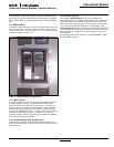
1.3.2 Magnum Drawout Switching Devices
The Magnum drawout switching device is a design having three
positions with the compartment door closed (CONNECT, TEST,
DISCONNECT) and one position out of its compartment on the
extendable carriage rails (REMOVE). The Magnum drawout
switching device is equipped with both primary and secondary dis-
connects to provide for the drawout functioning. The operating
mechanism is a two-step, stored energy mechanism, either manu-
ally or electrically operated. When withdrawn on the extendable
carriage rails, Magnum switching devices can be inspected, acces-
sory items added, and minor maintenance performed. The inside
of the compartment can also be inspected with the switching
device withdrawn on the extendable carriage rails.
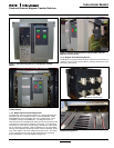
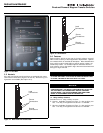
Figure 9. Drawout Switching Device Fully Extended from the
Magnum Transfer Switch.
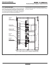
1.3.3 Magnum Fixed Switching Devices
The Magnum fixed type switching device differs from the drawout
version in that it has no levering device, primary disconnects, and
secondary disconnects.
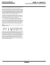
Figure 10. Primary and Secondary Connections on a Magnum
Fixed Switching Device.
PRIMARY CONNECTIONS
SECONDARY CONNECTIONS