For more information visit: www.Eaton.com IB01602011E
Instructional Booklet
Page 28 Effective: March 2007
Fixed and Drawout Magnum Transfer Switches
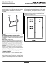
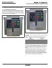
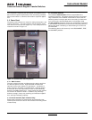
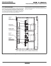
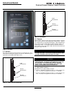
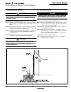
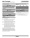
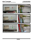
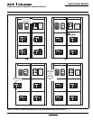
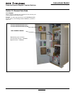
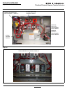
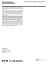
Figure 38. Transfer from Normal Switching Device to Normal Bypass Switching Device, Steps 5-6.
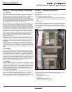
7.3.3 Source 1 to Source 2 Bypass (Open Transition Only)
The Source 1 switch can be isolated and bypassed by the follow-
ing sequence:
1. Move the generator selector switch to the RUN position
because the load needs to be energized from the Source 2
power source.
2. Make sure that the Source 2 power source is available.
3. Open the source/switching device.
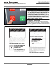
4. Close the Source 2 bypass switching device manually. The
Source 2 bypass light will be illuminated.
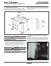
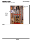
5. Rack out the Source 1 switching device (see Section 6). The
Source 1 isolated light will illuminate.
6. Inspect and/or perform the needed maintenance on the
Source 1 switching device.
7. Rack in the Source 1 switching device (see Section 6). The
Source 1 switching device will automatically recharge when it
is in the CONNECT position. The Source 1 isolated light will
no longer be illuminated.
8. Open the Source 2 bypass switching device. The Source 2
bypass light will no longer be illuminated.
9. The Source 1 switching device is now back in automatic oper-
ation.
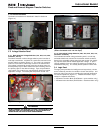
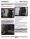
7.3.4 Source 2 to Source 1 Bypass (Open Transition Only)
The Source 2 switching device can be bypassed and isolated by
the following sequence:
1. Ensure that the Source 1 power is available since the load will
be energized from the Source 1 power source.
2. Move the generator selector switch to the OFF position to
avoid nuisance starting of the generator while work is being
performed on the Source 2 switching device.
3. Open the Source 2 switching device.
4. Close the Source 1 bypass switching device manually. The
Source 1 bypass light will illuminate.
5. Rack out the Source 2 switching device (see Section 6). The
Source 2 isolated light will illuminate.
6. Inspect and/or perform the needed maintenance on the
Source 2 switching device.
7. Rack in the Source 2 switching device (see Section 6). The
Source 2 isolated light will no longer be illuminated.
8. Open the Source 1 bypass switching device. The
Source 1 light will no longer be illuminated.
9. The switching device is now back in automatic operation.
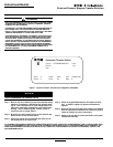
Cutler-Hammer
Digitrip 3000
Operational
High Load
Communications
Trip
Time Overcurrent
Curve Shape
Pickup (x In)
Time Multiplier
Pickup (x In)
Time
Program
Phase
Ground
I
I
I
RMS Amperes
Settings/Test Time/Trip Cause
Test
Program
Test
Pickup (x In)
Instantaneous
Short Delay
Amp Demand
I
Cutler-Hammer
Phase
Phase
Phase
Phase
Ground
Digitrip 3000
Operatio
High
Commun
Time Overcurrent
Curve Shape
Pickup (x In)
Time Multiplier
Time
Program
Phase
Ground
RMS
Settings/Test
Time/Trip Cause
Short Delay
Cutler-Hammer
Digitrip 3000
Operational
High Load
Communications
Trip
Time Overcurrent
Curve Shape
Pickup (x In)
Time Multiplier
Pickup (x In)
Time
Program
Phase
Ground
I
I
I
RMS Amperes
Settings/Test Time/Trip Cause
Test
Program
Test
Pickup (x In)
Instantaneous
Short Delay
Amp Demand
I
Cutler-Hammer
Phase
Phase
Phase
Phase
Ground
Digitrip 3000
Operatio
High
Commun
Time Overcurrent
Curve Shape
Pickup (x In)
Time Multiplier
Time
Program
Phase
Ground
RMS
Settings/Test
Time/Trip Cause
Short Delay
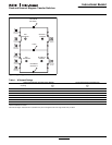
5
Source 1
6