


For more information visit: www.Eaton.com IB01602011E
Instructional Booklet
Page 20 Effective: March 2007
Fixed and Drawout Magnum Transfer Switches
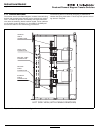
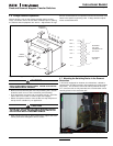
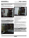
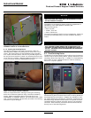
Carefully lower the circuit breaker down onto the extension rails.
Be certain that the circuit breaker’s four molded drawout rail sup-
ports are fully seated in the extension rail cutouts on both sides
(Figure 22). Do not remove the lifting yoke from the circuit
breaker until it is properly seated on the rails.
Once the circuit breaker is on the extension rails and the lifting
yoke is removed, proceed with the rest of the circuit breaker
installation.
4.8 Wiring
Power sources, load conductors, and control wiring should be
connected to locations as indicated in the Customer Wiring Dia-
grams supplied with the transfer switch equipment.
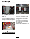
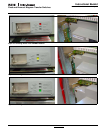
4.8.1 Engine Start Connection
The engine control contact connections are located on the
ATC-600/ATC 800 Controller. The engine control contact con-
nections of bypass isolation units are located in the door of the
enclosure
Note: Prior to making the engine start connection to the switch on bypass
isolation units, set the engine generator controls selector switch in the OFF
position to prevent an unwanted engine start. A contact closes between
these terminal blocks when an engine start signal is provided by the ATS
logic.
4.8.2 ALARM CONTACTS (CLOSED TRANSITION ONLY)
Closed transition only ATSs are provided with an extra shunt trip
on the Source 1 device. This shunt trip is energized when the
Time Delay Utility Parallel (TDUP) times out (preset by user), thus
opening the source device. The TDUP timer starts timing when
both sources are paralleled. Refer to the IQ Transfer instruction
book for additional alarms.
Section 5: Operation
5.1 General
A transfer switch provides main contacts to connect and discon-
nect the load to and from the Source 1 and Source 2 power
sources. A stored-energy type transfer mechanism provides the
mechanical motion required to open and close the main contacts
(Paragraph 3.2.1).
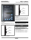
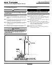
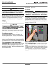
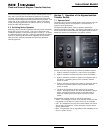
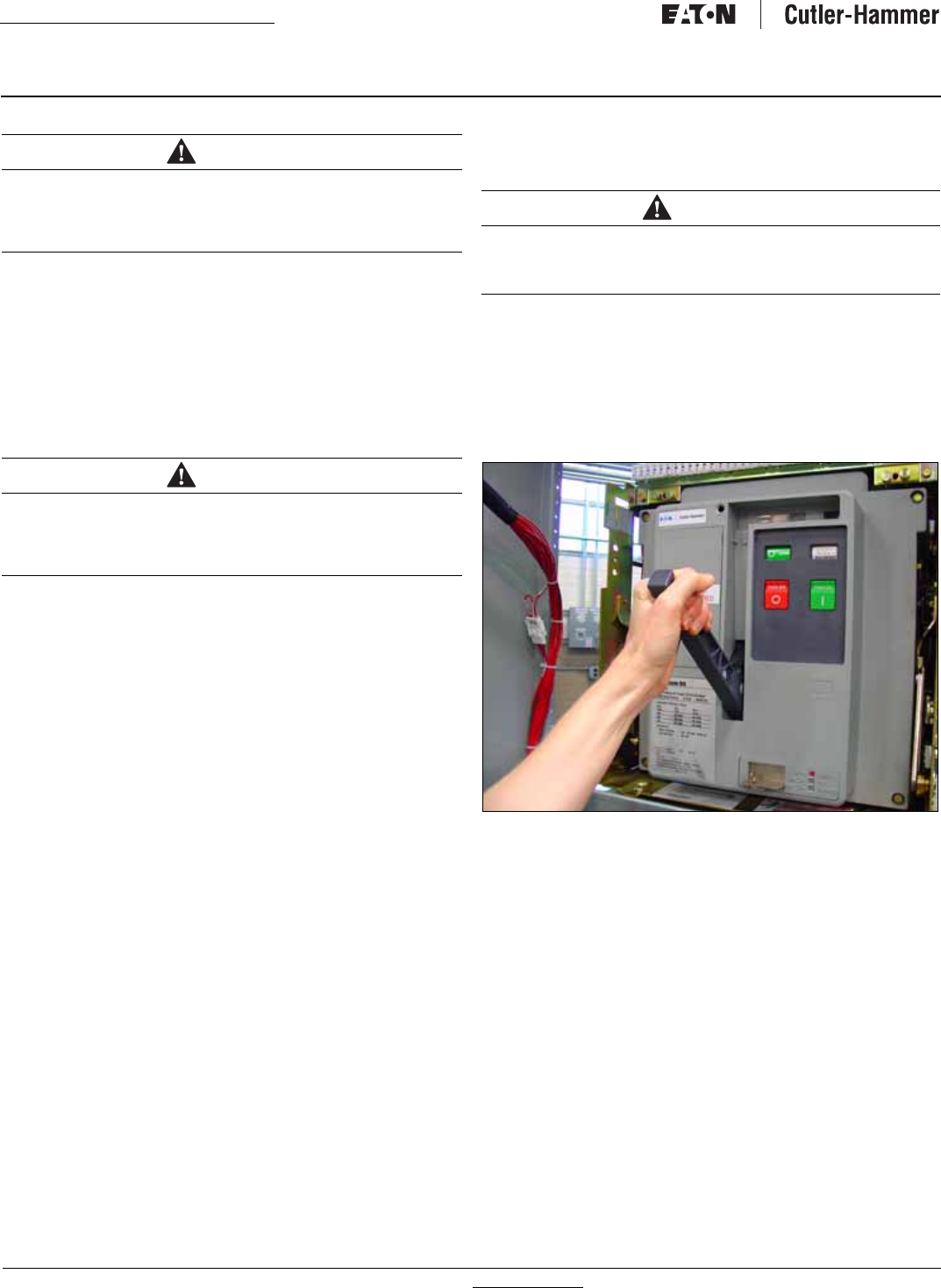
Each switch can be manually operated. Before a switching device
can be closed, the stored energy mechanism must be charged by
pumping the handle (Figure 23).
Figure 23. Pumping Handle Charges Stored Energy Mechanism
(Closed Transition Shown).
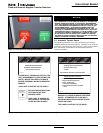
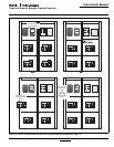
In the closed transition product, a single switching device can be
manually closed by following the instructions detailed in Figure
25. An indicator window shows whether the switch is open or
closed.
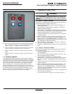
The open transition switching device can be closed by pushing the
close button (Figure 24). The other switching device is prevented
from closing through a rigid mechanical interlock (Paragraph
3.2.2). An indicator window shows whether the switch is open
or closed.
CAUTION
IT IS IMPORTANT TO TAKE GREAT CARE WHEN PLACING A DRA-
WOUT CIRCUIT BREAKER ON ITS EXTENSION RAILS. IF THE CIR-
CUIT BREAKER IS NOT PROPERLY SEATED ON THE EXTENSION
RAILS, IT COULD FALL FROM THE RAILS CAUSING EQUIPMENT
DAMAGE AND/OR BODILY INJURY.
CAUTION
POWER CONDUCTORS AND CONTROL WIRING MAY HAVE VOLT-
AGE PRESENT THAT CAN CAUSE SEVERE PERSONAL INJURY OR
DEATH. DE-ENERGIZE ALL POWER OR CONTROL CIRCUIT CONDUC-
TORS BEFORE BEGINNING TO PERFORM ANY WIRING ACTIVITY TO
OR WITHIN THE TRANSFER SWITCH EQUIPMENT.
WARNING
THE CLOSED TRANSITION PRODUCT CONTAINS A SPECIAL CON-
TACT ARRANGEMENT (OVERLAPPING CONTACTS). MISUSE CAN
RESULT IN DEATH, SEVERE PERSONAL INJURY, AND/OR PROPERTY
DAMAGE.