


IB01602011E For more information visit: www.Eaton.com
Instructional Booklet
Effective: March 2007 Page 25
Fixed and Drawout Magnum Transfer Switches
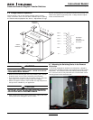
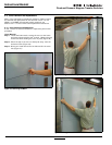
The fixed switching device frame has two mounting feet, one on
each side, to permit the fixed switching device to be securely
mounted. Each mounting foot has two slotted mounting holes
which are used to bolt the switching device securely in place. Use
either 3/8” or M 10 bolts for this purpose. Refer to the dimen-
sional drawings supplied with the transfer switch for switching
device and bus stab dimensions.
6.3 Switching Device Operation
Switching devices should be operated manually and/or electrically
before they are put into service. This can be done during the
installation process or some later date prior to start-up. To check
the switching device operation, follow the operational procedures
outlined in switching device manual supplied with the transfer
switch for both manually operated and electrically operated
switching devices.
Section 7: Operation of the Bypass Isolation
Transfer Switch
7.1 Operator Panel
The design of this transfer switch allows quick removal of the dif-
ferent switching devices for inspection or maintenance or, if
required, quick replacement.
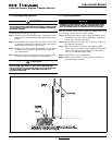
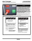
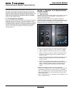
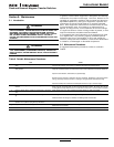
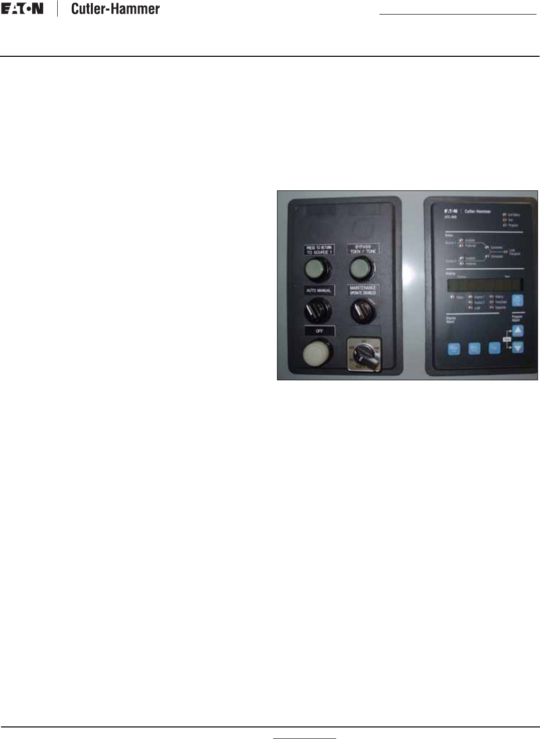
The bypass isolation switch has two operator panels with
switches and lights (Figure 35). The following descriptions are for
those features that are standard with the bypass isolation switch.
Additional features are described in the options section.
Figure 35.Bypass Isolation Switch.
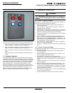
The left door control panel has the following standard features:
1. Light to indicate if the Source 1 power source is available.
2. Light to indicate if the Source 2 power source is available.
3. Light to indicate if the Source 1position is energized, that is,
the Source 1 switching device in the automatic transfer
switch is closed.
4. Light to indicate if the Source 2 position is energized, that is,
the Source 2 switching device in the automatic transfer
switch is closed.
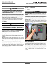
5. The Push-To-Test button allows testing of the transfer
switch. Pushing the button two times will simulate a power
failure, causing the transfer switch to start the transfer
sequence. Pressing the button again will restore regular
power.
Three-position selector switch to control the generator:
• AUTO - The intelligence circuit of the transfer switch will start
the generator if the Source 1 power source is not available.
• OFF - The intelligence circuit of the transfer switch will not be
able to start the generator, which eliminates nuisance starts
during maintenance.
• RUN - The generator will run regardless of the availability of the
Source 1 power source.