


For more information visit: www.Eaton.com IB01602011E
Instructional Booklet
Page 30 Effective: March 2007
Fixed and Drawout Magnum Transfer Switches
If a problem persists after having completed the problem solving
procedure, contact an Eaton representative for further assistance.
When calling for assistance, the following is the MINIMUM infor-
mation required to properly address the need:
1. Shop Order Number (SO #) or General Order Number
(GO #) of the transfer switch, plus related Item Number;
2. Catalog and/or Style Number of the transfer switch;
3. Actual location of transfer switch (type of facility, address,
etc.);
4. Company name;
5. Name and position of individual representing company;
6. Basic description of situation as it exists; and
7. Any results of problem solving steps taken and/or readings
taken.
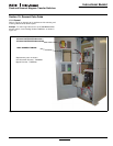
8.2.1 Transfer Switch Appears Inoperative
Step 1: Verify that all plugs and sockets are properly intercon-
nected.
Step 2: Verify that the correct system voltage appears at
Source 1 switch. Measure the voltage at the breaker
lugs.
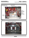
Step 3: Verify that the voltage selection plug is in the proper posi-
tion to match the system voltage.
Step 4: Look for any obviously burned components. Determine
the cause and rectify, if possible. Replace any defective
components after the cause is determined.
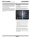
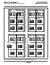
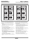
Step 5: For closed transition, refer to Figure 25 for manual oper-
ating instructions. Verify whether or not the system volt-
age now appears on the load terminals.
If YES: Check the logic for problems in the respective
logic instruction book.
If NO: Check all power connections and the switching
mechanism.
Step 5: For open transition, press the Push-To-Close button on
the Source 1 switching device. Verify whether or not the
system voltage now appears on the load terminals.
If YES: Check the logic for problems in the respective
logic instruction book.
If NO: Check all power connections and the switching
mechanism.
8.2.2 Transfer Switch Will Not Automatically Transfer to
Source 1
Step 1: Check for the proper line voltage on N1, N2, and N3.
Step 2: Is the Source 1 switching device charged?
If YES: Continue with the other procedures.
If NO: Go through section 8.2.4 first before continuing.
Step 3: Is the Source 2 switch OPEN?
If YES: Proceed to Step 5.
If NO: Proceed to Step 4.
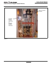
Step 4: Measure the voltage between terminals S2B1O and
S2B11 on the Source 2 switching device (shunt trip).
Does the voltage measure 120 Vac ±10 volts? Record
the reading.
If YES: Check the shunt trip in the Source 2 switch.
If NO: Check the wiring to S2B10 and S2B11.
Step 5: Measure the voltage between terminals S1B12 and
S1B13 on the Source 1 switching device (spring release
coil). Does the voltage measure 120 Vac ± 10 volts?
Record the reading.
If YES: Check the spring release coil in Source 1 switch-
ing device.
If NO: Check the wiring to S1B12 and S1B13.
8.2.3 Transfer Switch Will Not Automatically Transfer to
Source 2
Step 1: Check for the proper line voltage on E1, E2, and E3.
Step 2: Is the Source 2 switching device charged?
If YES: Continue with the other procedures.
If NO: Go through Section 8.2.4 first before continuing.
Step 3: Is the Source 1 switching device OPEN?
If YES: Proceed to Step 5.
If NO: Proceed to Step 4.
Step 4: Measure the voltage between terminals S1B10 and
S1B11 on the Source 1 switching device (shunt trip).
Does the voltage measure 120 Vac ± 10 volts? Record
the reading.
If YES: Check the shunt trip in the Source 1 switch.
If NO: Check the wiring to S1B10 and S1B11.
Step 5: Measure the voltage between terminals S2B12 and
S2B13 on the Source 2 switching device (spring release
coil). Does the voltage measure 120 Vac+
10 volts?
Record the reading.
If YES: Check the spring release coil in Source 2 switch.
If NO: Check the wiring to S2B12 and S2B13.
8.2.4 Transfer Switch Will Not Automatically Recharge Switches
Step 1: Measure the voltage between terminals B15 and B14 on
the switching device that does not automatically
recharge. Does the voltage read 120 Vac +
10 volts?
Record the reading.
If YES: Check the electrical operator inside the switching
device.
If NO: Verify the wiring to B15 and B14.
Step 2: If problem persists, contact Eaton.
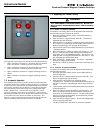
WARNING
THIS CLOSED TRANSITION PRODUCT CONTAINS A SPECIAL CON-
TACT ARRANGEMENT (OVERLAPPING CONTACTS). MISUSE CAN
RESULT IN DEATH, SEVERE PERSONAL INJURY, AND/OR PROPERTY
DAMAGE.