


For more information visit: www.Eaton.com IB01602011E
Instructional Booklet
Page 24 Effective: March 2007
Fixed and Drawout Magnum Transfer Switches
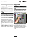
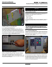
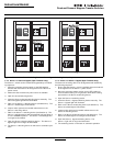
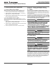
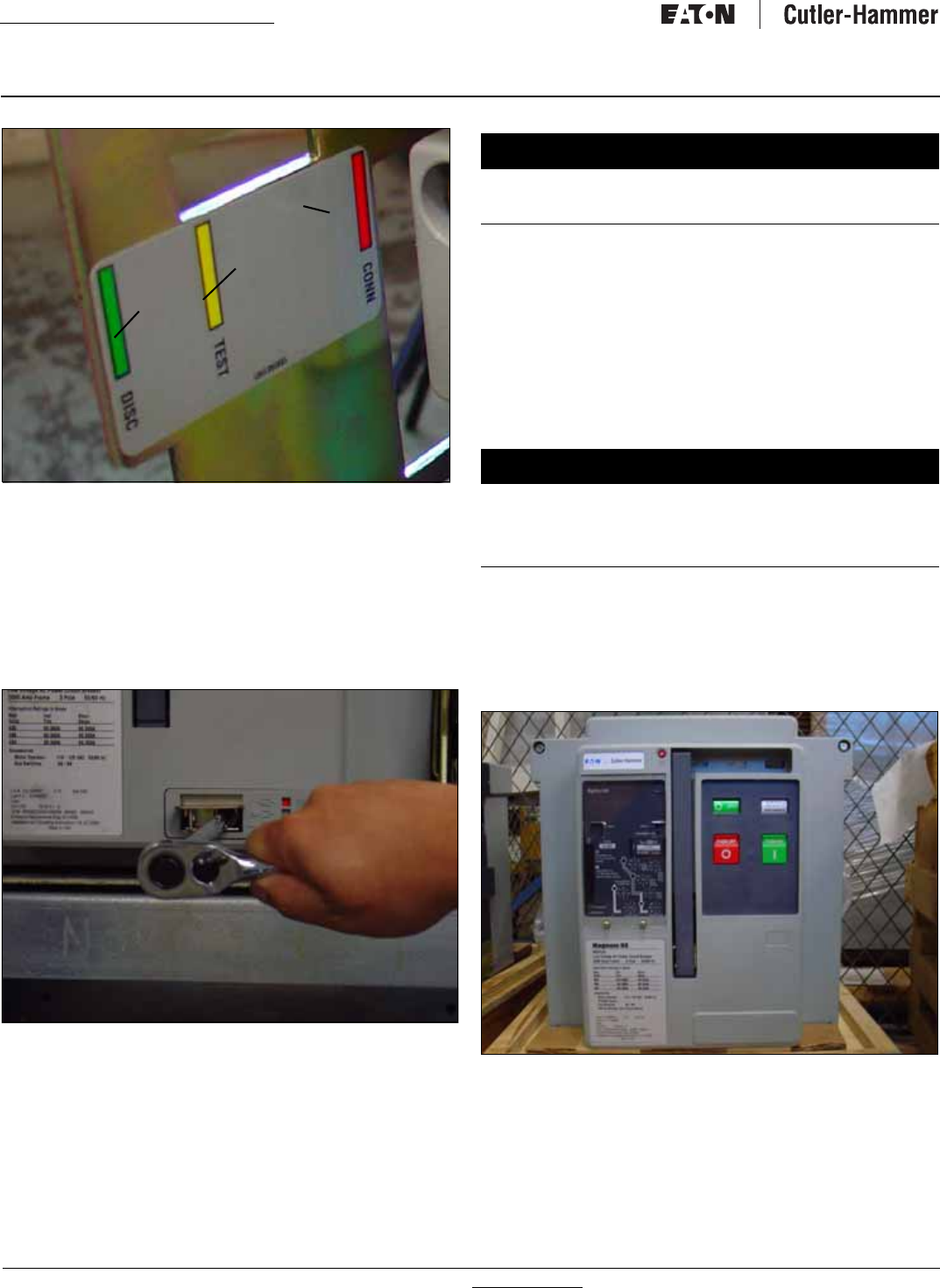
Figure 32.Carriage Label Showing DISCONNECT, TEST, and
CONNECT Positions of the Recessed Cover.
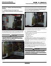
6.1.2 Levering the Switching Device
The switching device is now ready to be levered. With the
switching device OPEN, the levering device access door can be
raised. The levering device is hand operated using a standard
3/8” square drive and ratchet, which is not provided (Figure 33).
As long as the access door is raised, the switching device is held
in the “trip free” condition. Begin by rotating the levering-in screw
to the full counter clockwise (DISCONNECT) position.
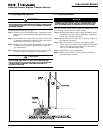
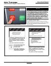
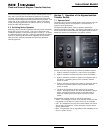
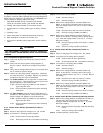
Figure 33.Levering and Position Indication.
Close the compartment door and begin levering the switching
device into its different positions using a clockwise ratcheting
motion. When the switching device is levered fully to the
DISCONNECT or CONNECT position, the levering shaft hits a hard
stop. Do NOT exceed 25 ft lb (33.9 Nm) of torque or the levering
mechanism may be damaged.
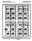
The position of the switching device within its compartment is
indicated by color coded position indicators (See
Figure 29 through 32):
• Red=Connect;
• Yellow=Test; and
• Green=Disconnect.
To remove the switching device from its compartment, follow the
procedure just described using a counter clockwise ratcheting
motion.
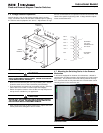
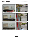
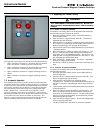
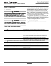
6.2. Fixed Switching Device
The Magnum fixed type switching device differs from the drawout
version in that it has no levering device, primary disconnects, and
secondary disconnects (Figure 34). In addition, a fixed switching
device does not have a standard feature to hold the switching
device in a “trip free” position
Figure 34. Typical Magnum Fixed Switching Device.
Fixed switching device terminals have holes for making bolted hor-
izontal primary bus connections. Adapters are available for mak-
ing vertical primary bus connections. Secondary connections can
be made through standard terminal blocks or a special connector
compatible with the drawout switching device’s type secondary
connector. Both secondary connection devices are mounted at
the top front of the switching device.
Red
Yellow
Green
NOTICE
THE SWITCHING DEVICE CAN BE LEVERED WITH THE COMPART-
MENT DOOR OPEN OR CLOSED, BUT IT IS ADVISABLE TO CLOSE
THE DOOR PRIOR TO LEVERING.
NOTICE
THE SWITCHING DEVICE MECHANISM IS INTERLOCKED SUCH
THAT CHARGED CLOSING SPRINGS ARE AUTOMATICALLY DIS-
CHARGED IF THE SWITCHING DEVICE IS LEVERED INTO OR OUT OF
THE CELL. DISCHARGE TAKES PLACE BETWEEN THE DISCONNECT
AND TEST POSITION.