


For more information visit: www.Eaton.com IB01602011E
Instructional Booklet
Page 4 Effective: March 2007
Fixed and Drawout Magnum Transfer Switches
Basic Transfer Switch (Power Panel)
The basic transfer switch is designed for use with customer fur-
nished logic. It is similar in design to the automatic version,
except the intelligence circuit (logic panel) and voltage selection
panel are omitted. All control devices are the customer’s
responsibility.
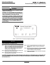
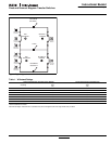
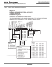
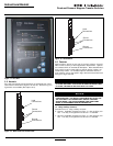
Figure 2. Typical Load Transfer Switch (Switching Device Type)
Schematic.
Non-Automatic Transfer Switch (Electrically Operated)
Non-automatic transfer switches are manually initiated, electrically
operated devices for applications where automatic load transfer is
not required.
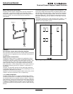
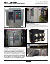
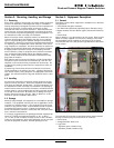
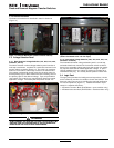
Bypass Isolation Transfer Switch
The bypass isolation switch is designed for applications where
maintenance, inspection, and testing must be performed while
maintaining continuous power to the load (Figures 3 and 4). This
is typically required in critical life support systems and standby
power situations calling for safe system maintenance with no
power disruptions. Such a design allows for the quick removal of
the different switching devices for inspection, maintenance, or
replacement.
The ATS, non-automatic transfer switch (electrically operated),
and bypass isolation transfer switch are the available types for the
configuration described in this manual.
Operation of the ATS and the bypass isolation switch only are dis-
cussed in this manual (Sections 5 and 7 respectively).
1.2.2 Design Configuration
The Eaton transfer switch is a rugged, compact design utilizing
insulated case switches or insulated case circuit breakers to trans-
fer essential loads from one power source to another. Open tran-
sition switching devices are interlocked to prevent both switching
devices from being closed at the same time. The versatile design,
in addition to standard transfer functions, offers an optional inte-
gral thermal and short circuit protection in either or both switching
devices.
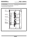
The switching devices are in a compact vertical arrangement. The
logic can be easily disconnected from the switching device with-
out disturbing critical connections. The enclosure is free standing,
and, by using the specially supplied cleats, the switch is seismic
approved (Option 42). The terminals are mounted in the rear of
the switch, permitting rear, top, bottom, or side cable or bus bar
entrance.
The switching devices have a high withstand rating (Table 1). The
high-speed, stored-energy switching mechanism guarantees a
transfer time of less than 5 cycles.
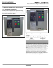
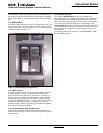
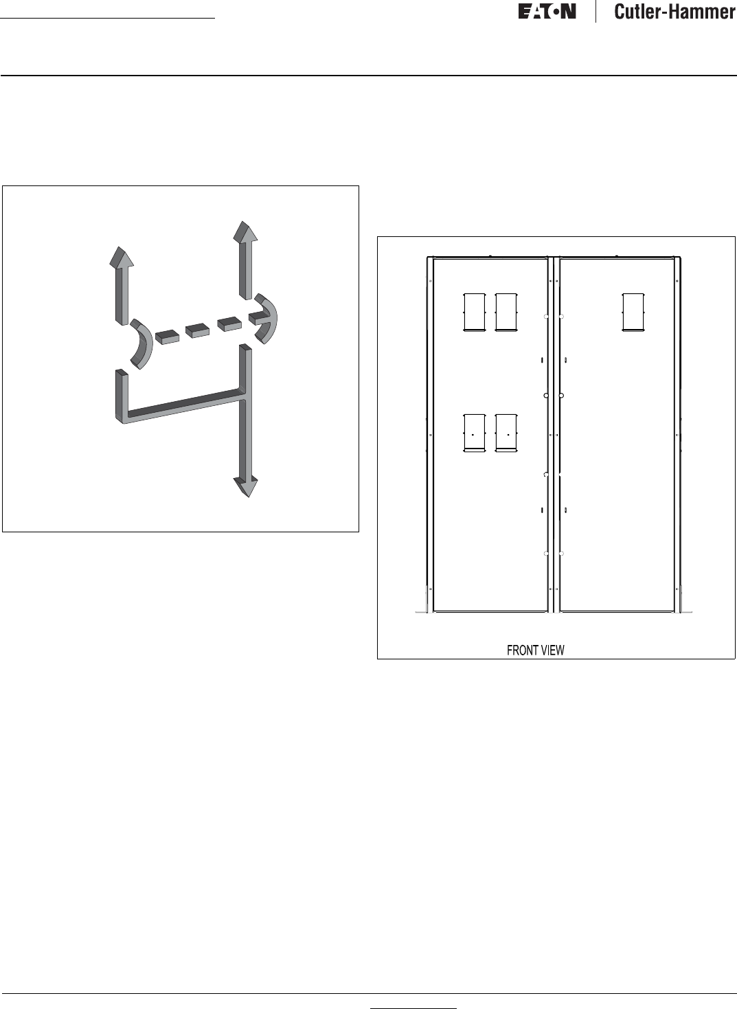
Figure 3.Typical Bypass Isolation Switch.
Source 1
Source 2
Load