


For more information visit: www.Eaton.com IB01602011E
Instructional Booklet
Page 16 Effective: March 2007
Fixed and Drawout Magnum Transfer Switches
3.8 Standards
Eaton transfer switch equipment is listed for application by UL and
CSA. In addition, Eaton ATSs are listed in File E38116 by
UL, Inc., under Standard UL 1008. This standard covers require-
ments for ATSs intended for use in ordinary locations to provide
for lighting and power as follows:
a. In emergency systems, in accordance with articles 517 and
700 in the National Electrical Code (NEC), American National
Standards Institute/National Fire Protection Association
(ANSI/NFPA) 70 and the NFPA No. 76A and/or
b. In stand-by systems, in accordance with article 702 of the
NEC and/or
c. In legally required stand-by systems in accordance with article
701 of the NEC.
Eaton ATSs are available to meet NFPA 110 for emergency and
stand-by power systems, and NFPA 99 for health care facilities
when ordered with the appropriate options.
Since Eaton ATSs utilize specially designed switches and/or
switching devices as the main power switching contacts, these
devices must also be listed under the additional UL Standard
1066. UL utilizes two basic types of listing programs: a) Label
Service and b) Re-examination. UL1066 employs a label service
listing program which requires an extensive follow-up testing pro-
gram for listed devices. Standard UL1008 for ATSs lists devices
under the re-examination program which only requires a continual
physical re-examination of the components used in the product to
insure consistency with the originally submitted device. Follow-up
testing IS NOT required by UL1008.
Representative production samples of switches and switching
devices used in Eaton ATSs are subjected to a complete test pro-
gram identical to the originally submitted devices on an ongoing
periodic basis per UL1066. The frequency of such a re-submittal
can be as often as every quarter for a low ampere device.
Section 4: Installation and Wiring
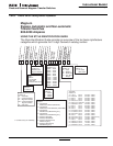
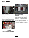
4.1 General
Eaton transfer switches are factory wired and tested. Installation
requires solidly mounting the enclosed unit and connecting the
power cables and auxiliary pilot circuits. Physical mounting proce-
dures and power cable connections are covered in this section.
All other required wiring or electrical connection references are
covered in a separate Customer Wiring Diagram packaged with
the transfer switch.
Locate the wiring booklet, review it, and keep it readily available
for reference purposes during installation and testing. Once a
transfer switch is properly installed and wired, it should be
mechanically and electrically checked for proper installation and
operation. The procedures for these initial mechanical and electri-
cal checks are outlined in Section 8.1 of this instruction manual.
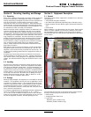
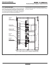
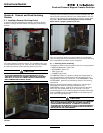
4.2 Mounting Location
Choose a location that offers a flat, rigid mounting surface capa-
ble of supporting the weight of the enclosed transfer switch
equipment. Avoid locations that are moist, hot, or dusty. How-
ever, Eaton offers enclosure designs that can be used in special
environments. If there are any doubts as to the suitability of the
location, discuss it with your Eaton representative.
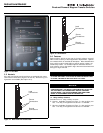
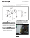
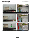
Check to make certain that there are no pipes, wires, or other haz-
ards in the immediate area that could create a problem. The pan-
els provide ample room for rear cable entry from top, bottom, and
sides. At no time should cable be routed to retard the action of
relays or cover the logic in a way that restricts adjustments.
Maintain proper electrical clearances between live metal parts and
grounded metal.
For installation and maintenance purposes, the Source 1 and
Source 2 power sources must have an overcurrent protective
device upstream of the transfer switch, unless overcurrent protec-
tion is integral to the switch.
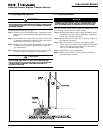
The dimensions of the transfer switch are an important consider-
ation in determining proper location selection.
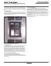
WARNING
BE CERTAIN THAT THE SOLID STEEL POWER PANEL SHIELDS ARE
PROPERLY INSTALLED BEFORE THE TRANSFER SWITCH EQUIP-
MENT IS PUT INTO SERVICE. THE SHIELD PROVIDES PROTECTION
FROM DANGEROUS VOLTAGES AT THE LINE AND LOAD TERMI-
NALS WHEN THE EQUIPMENT IS IN OPERATION. FAILURE TO DO
SO COULD RESULT IN PERSONAL INJURY OR DEATH.