


IB01602011E For more information visit: www.Eaton.com
Instructional Booklet
Effective: March 2007 Page 18
Fixed and Drawout Magnum Transfer Switches
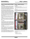
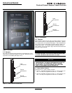
4.5 Power Cable Connections
Proceed with the following steps:
Step 1: Verify that the line and load cables comply with applica-
ble electrical codes.
Step 2: Verify that the transfer switch rated current and voltage
(see identification plate on the door of the transfer
switch) agree with system current and voltage.
Step 3: After the transfer switch is mounted, provide the conduit
or cable openings as required. Ensure that no metal filings
contaminate the transfer switch components.
Step 4: Test all power cables before connecting them to the unit
to insure that the conductors or the cable insulation have
not been damaged while being pulled into position.
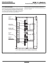
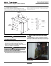
Step 5: Carefully strip the insulation from the power cables.
Avoid nicking or ringing of the conductor strands. Pre-
pare the stripped conductor termination end by cleaning
it with a wire brush. If aluminum conductors are used,
apply an appropriate joint compound to the clean conduc-
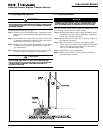
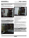
tor surface area. Refer to Figure 13 for the approximate
locations of the power connections.
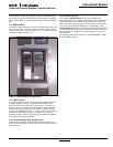
Power cables are to be connected to solderless screw type lugs
located on the transfer switch switching devices. Refer to the
separate Customer Wiring Diagrams supplied with the transfer
switch equipment for power termination. Verify that the lugs sup-
plied will accommodate the power cables being used. Also verify
that the cables comply with local electrical codes. Standard trans-
fer switch equipment, as supplied from the factory, will accommo-
date the wire sizes shown in Table 5.
Table 5. Wire Size for Available Power Cable
Connections.
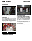
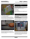
Step 6: Tighten the cable lugs to the torque identified on the label
affixed to the door.
Step 7: Make the necessary connections of any options using the
wiring diagrams supplied with the unit.
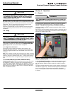
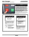
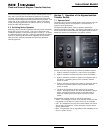
Step 8: Connect the engine start wires to the logic connector
J5-1 & J5-2 on the ATC-600/ATC-800 Controller.
WARNING
POWER CONDUCTORS MAY HAVE VOLTAGE PRESENT THAT CAN
CAUSE SEVERE PERSONAL INJURY OR DEATH. DE-ENERGIZE ALL
POWER OR CONTROL CIRCUIT CONDUCTORS TO BE CONNECTED
TO THE TRANSFER SWITCH EQUIPMENT BEFORE BEGINNING TO
WORK WITH THE CONDUCTORS AND/OR TERMINATING THEM TO
THE EQUIPMENT.
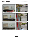
CAUTION
USE OF CABLE LUGS NOT DESIGNED FOR THE TRANSFER SWITCH
APPLICATIONS MAY CAUSE HEATING PROBLEMS. BREAKER LUGS
ONLY MOUNT TO THE BREAKER, WHILE TRANSFER SWITCH LUGS
MOUNT TO BOTH THE BREAKER AND THE BUS BAR BEHIND THE
BREAKER. FOR INSTALLATION INSTRUCTIONS, REFER TO THE
INSTRUCTION LEAFLET SUPPLIED FOR THE SPECIFIC LUGS.
CAUTION
TO HELP PREVENT COMPONENT DAMAGE OR FUTURE MALFUNC-
TIONS, USE EXTREME CARE TO KEEP CONTAMINANTS OUT OF THE
TRANSFER SWITCH EQUIPMENT WHEN MAKING POWER CABLE
CONNECTIONS.
DEVICE SWITCH
RATING
(AMPS)
CABLES
PER
PHASE
RANGE
WIRING SIZE
Switch 800-2000 6 3/0-750 MCM
Switch 2500-3200 9 3/0-750 MCM
Neutral 800-2000 24 4/0-500 MCM
Neutral 2500-3200 36 4/0-500 MCM
CAUTION
IMPROPER POWER CABLE CONNECTIONS CAN CAUSE EXCESSIVE
HEAT AND SUBSEQUENT EQUIPMENT FAILURE.