


For more information visit: www.Eaton.com IB01602011E
Instructional Booklet
Page 22 Effective: March 2007
Fixed and Drawout Magnum Transfer Switches
Section 6: Drawout and Fixed Switching
Devices
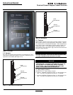
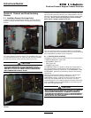
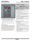
6.1 Installing a Drawout Switching Device
In transfer switches equipped with drawout switching devices,
bolted-in carriages with extendable rails support the switching
devices.
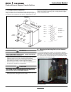
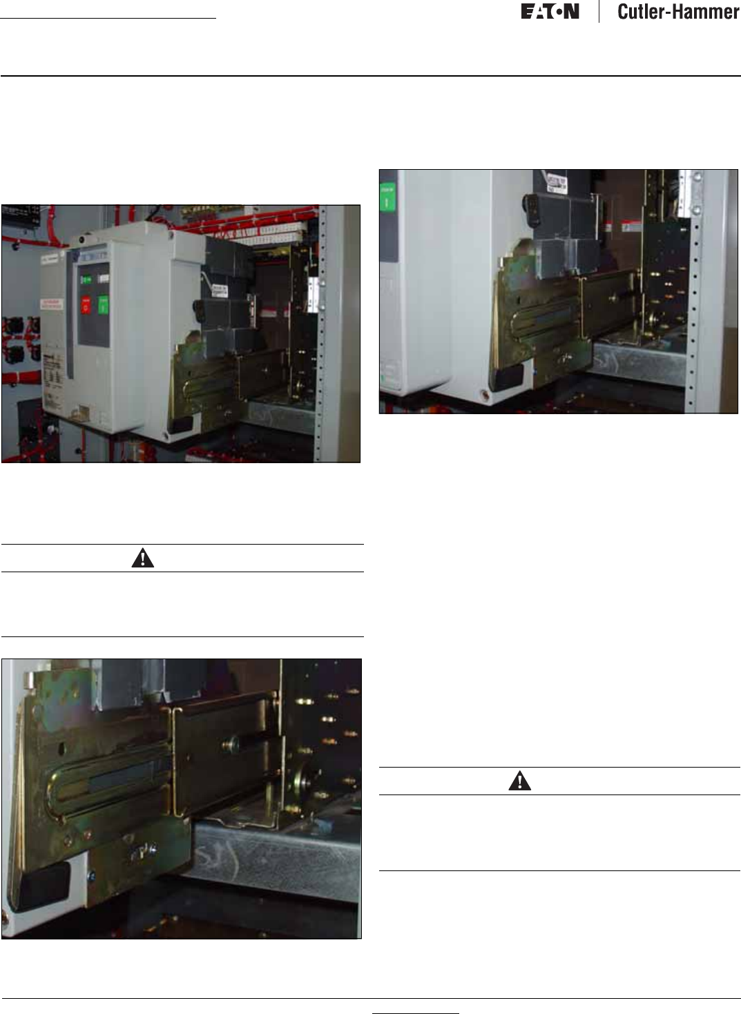
Figure 26. Switching Device Drawn Out from the Transfer Switch.
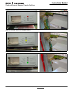
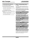
To install a drawout switching device, the extendable rails must
first be pulled all the way out. Once the rails are fully extended,
the switching device can be carefully placed on the rails.
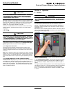
Figure 27. Drawout Rail Supports Fully Seated in the Rail
Cutouts.
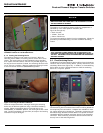
Carefully lower the switching device onto the extended rails. Be
certain that the switching device’s four molded drawout rail sup-
ports are fully seated in the extendable rail cutouts on both sides
(Figure28). Do not remove the lifting yoke from the switching
device until it is properly seated on the rails.
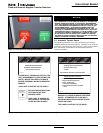
Figure 28. Switching Device in the REMOVE Position.
Once the switching device is properly seated on the extended
rails, the lifting yoke can be removed and the rest of the switching
device installation procedure can be completed.
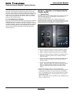
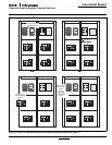
6.1.1 Switching Device Positioning
The Magnum drawout switching device has four normal positions:
• REMOVE (Withdrawn) (Figure 28)
• DISCONNECT (Figure 31)
• TEST (Figure 30)
• CONNECT (Figure 29)
The REMOVE position is a position outside the compartment on
the carriages drawout rails where the switching device is not
engaged with the levering mechanism. The DISCONNECT, TEST,
and CONNECT, positions are reached by means of the levering
mechanism.
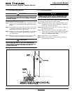
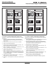
With the switching device solidly positioned on the carriage’s
extendable rails and the levering-in mechanism in the
DISCONNECT position, carefully and firmly push the switching
device into the compartment as far as it will go. The outer
(recessed) portion of the switching device face plate should align
with the GREEN target line (labeled DISC) on the inside top left
wall of the carriage (Figure 32).
CAUTION
IT IS IMPORTANT TO TAKE GREAT CARE WHEN PLACING A DRA-
WOUT SWITCHING DEVICE ON ITS EXTENDED RAILS. IF THE
SWITCHING DEVICE IS NOT PROPERLY SEATED ON THE EXTEND-
ABLE RAILS, IT COULD FALL FROM THE RAILS CAUSING EQUIP-
MENT DAMAGE AND/OR BODILY INJURY.
CAUTION
MAKE CERTAIN THAT THE SWITCHING DEVICE IS FULLY INSERTED
INTO ITS COMPARTMENT BEFORE ANY ATTEMPT IS MADE TO
LEVER THE SWITCHING DEVICE. ATTEMPTING TO LEVER THE
SWITCHING DEVICE IN BEFORE IT IS FULLY POSITIONED INSIDE ITS
COMPARTMENT CAN RESULT IN DAMAGE TO BOTH THE SWITCH-
ING DEVICE AND THE COMPARTMENT.