


IB01602011E For more information visit: www.Eaton.com
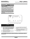
Instructional Booklet
Effective: March 2007 Page 5
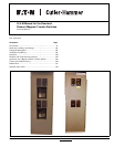
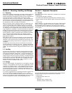
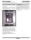
Fixed and Drawout Magnum Transfer Switches
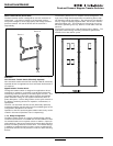
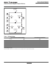
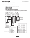
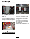
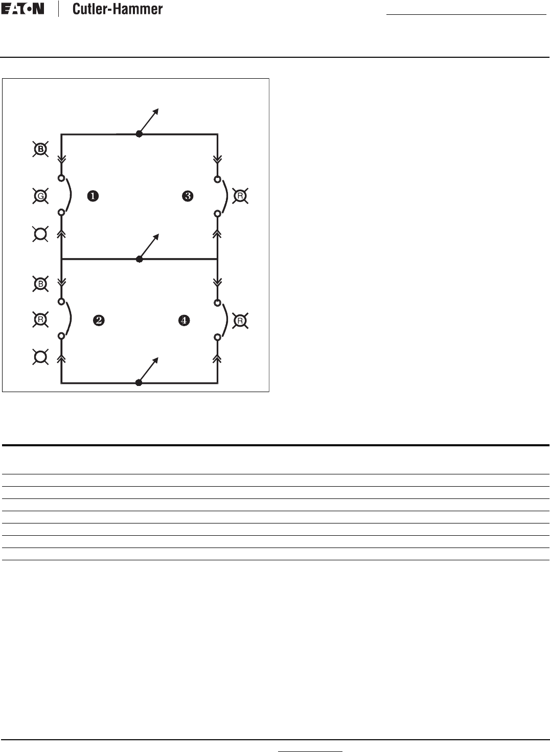
Figure 4.Typical Bypass Isolation Switch Schematic.
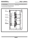
Table 1. Withstand Ratings
Tested in accordance with UL1008.
Eaton Drawout Magnum Transfer Switch will coordinate with a power switching device short time rating. Contact factory for details.
SOURCE 1
SOURCE 1
SOURCE 1
SOURCE 1
BYPASS
SOURCE 1
SOURCE 1
SOURCE 1
AVAILABLE
SOURCE 2
ISOLATED
ISOLATED
POSITION
SOURCE 2
POSITION
SOURCE 2
AVAILABLE
SOURCE 2
SOURCE 2
SOURCE 2
INCOMING
ATS
BYPASS
BYPASS
ATS
LOAD
SOURCE 2
BYPASS
INCOMING
A
A
RATING WHEN USED WITH UPSTREAM CIRCUIT BREAKER RATING WHEN USED WITH UPSTREAM FUSE
Transfer Switch
Amp Rating
3 Cycle
600V
(kA)
30 Cycle
600V
(kA)
800 100 85
1000 100 85
1200 100 85
1600 100 85
2000 100 85
2500 100 85
3200 100 85