


IB01602011E For more information visit: www.Eaton.com
Instructional Booklet
Effective: March 2007 Page 15
Fixed and Drawout Magnum Transfer Switches
15. Auxiliary Contacts
Position indication contacts provide Form “A and “B” position con-
tacts.
E. Source 1 Position: Provides one Form “A” and one Form “B”
contact per customer connection.
F. Source 2 Position: Provides one Form “A” and one Form “B”
contact for customer connection.
16. Integral Overcurrent Protection
Provides thermal-magnetic overcurrent protection integral to the
power switching device(s). All Feature 16 options include a
“Lockout” function. If the power switching device trips on an
overcurrent condition, then “Lockout” is displayed on the ATS
Controller display and automatic operation is prevented until the
appropriate source is manually reset.
B. Both Power Source Switching Devices: Provides integral over-
current protection on both Source 1 and Source 2 power
switching devices.
E, Source 2 Power Switching Device: Provides integral overcur-
rent protection on the Source 2 power switching device only.
N. Source 1 Power Switching Device: Provides integral overcur-
rent protection on the Source 1 power switching device only.
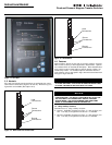
18. Metering and Communications
The IQ Family of microprocessor-based multi-function monitoring
and display devices features the latest technological advances in
metering and communications capabilities. Feature 18 metering
options include all required external devices (CT’s etc.) for a fully
functioning metering system.
O. IQ Analyzer - Source 1 Line Side Metering: Provides an IQ Ana-
lyzer for monitoring the Source 1 line side circuit.
P. IQ Analyzer - Source 2 Line Side Metering: Provides an IQ Ana-
lyzer for monitoring the Source 2 line side circuit.
Q. IQ Analyzer with Selector Switch for Source 1 or Source 2
Line Side Metering: Provides an IQ Analyzer with a source
selector switch for monitoring the Source 1 or Source 2 line
side circuit.
R. IQ DP-4000 - Source 1 Line Side Metering: Provides an IQ DP-
4000 for monitoring the Source 1 line side circuit.
S. IQ DP-4000 - Source 2 Line Side Metering: Provides an IQ DP-
4000 for monitoring the Source 2 line side circuit.
T. IQ DP-4000 with Selector Switch for Source 1 or Source 2
Line Side Metering: Provides an IQ DP-4000 with a source
selector switch for monitoring the Source 1 or Source 2 line
side circuit.
20A. Rear Bus Connections
Provides Source 1, Source 2, and Load Circuit rear accessible bus
stabs with provision for bus bar connection.
21A. Optional Power Cable Connection Terminals
Provides alternate power cable connection terminals. Consult
Eaton for available optional terminal sizes.
37. Service Entrance Rated Transfer Switch
Provides the label “Suitable for use as Service Equipment” and the
features necessary to meet the requirements for the label.
Includes service disconnect with visible indication and neutral
assembly with removable link. Feature 16 must be selected sepa-
rately.
A. Service Equipment Rated Transfer Switch without Ground
Fault Protection: Provides Service Equipment rating for an
application that does not require ground fault protection.
B. Service Equipment Rated Transfer Switch with Ground Fault
Protection: Provides Service Equipment rating for an applica-
tion that requires ground fault protection.
41. Space Heater with Thermostat
Provides a space heater and adjustable thermostat. External con-
trol power is not required.
C. Space Heater with Thermostat - 400 Watts: Provides a
400 Watt space heater with an adjustable thermostat.
42. Seismic Certification
Provides a Seismic Certified Transfer Switch with certificate for
application that is Seismic Zone 4 under the California Building
Code, the Uniform Building Code, and BOCA.
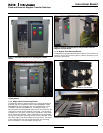
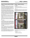
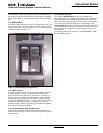
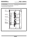
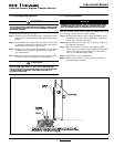
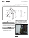
3.7 Enclosure
The rugged steel switch enclosure is supplied with four door
hinges, regardless of enclosure size, to insure proper support of
the door and door mounted devices. The hinges have removable
hinge pins to facilitate door removal. The doors are supplied as
standard with thumbscrew and padlock latches. Cable entry holes
are the customer’s responsibility.
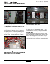
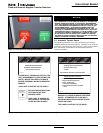
The door is used to mount a variety of lights, switches, and push
buttons, depending upon the options required for a particular
switch. All switch doors are supplied with a heavy duty plastic
accessory panel in place, whether or not external devices are
required. When lights, pushbuttons, or switches are required,
they are normally mounted in the plastic door mounted panel.
Transfer switch enclosures and some internal steel mounting
plates, such as the transformer panel mounting plate, go through
a pre-treatment cleaning system prior to painting to insure a dura-
ble finish. Should the enclosure become scratched and in need of
touch up paint, use ANSI 61. All remaining steel is galvanized.
The standard switch enclosure is NEMA Type 1 for general indoor
use (Table 4).
Table 4. Transfer Switch Equipment Enclosures.
NEMA TYPE DESIGN PROTECTION
1 Indoor Enclosed Equipment
3R Outdoor Rain, Ice Formation