


For more information visit: www.Eaton.com IB01602011E
Instructional Booklet
Page 26 Effective: March 2007
Fixed and Drawout Magnum Transfer Switches
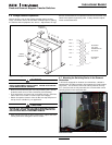
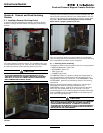
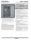
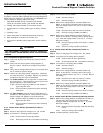
Figure 36. Magnum Bypass Lights.
The right door control panel has the following standard features:
1. Light to indicate if the Source 1 switching device is isolated
(only if the Source 1 switching device is racked out).
2. Light to indicate if the Source 2 switching device is isolated
(only if the Source 2 switching device is racked out).
3. Light to indicate if the Source 1 bypass switching device is
closed.
4. Light to indicate if the Source 2 bypass switching device is
closed.
7.2 Automatic Operation
The intelligence/supervisory circuits on Eaton transfer switches
constantly monitor the condition of both the Source 1 and Source
2 power sources. These circuits automatically initiate an immedi-
ate transfer of power from the Source 1 to the Source 2 power
source when the power source fails or the voltage level drops
below a preset value. Transfer back to the Source 1 power
source is automatic upon return of the Source 1 power source.
Monitoring the power source is always performed on the line side
of the power source to which the switch is connected. The
Source 1 power source is the preferred source and the transfer
switch will always seek this source when it is available.
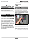
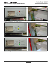
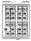
7.3 Bypassing the Transfer Switch
7.3.1 Source 1 to Source 1 BYPASS
The Source 1 switching device can be bypassed and isolated by
the following sequence (Figures 36 and 37):
1. Move the generator selector switch to the OFF position to
avoid nuisance starts.
2. Close the Source 1 bypass switch manually. The Source 1
bypassed light will illuminate.
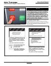
3. Open and rack out the Source 1 switching device (see Section
6). The Source 1 isolated light will illuminate and the Source 1
position energized light will no longer be illuminated.
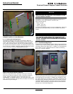
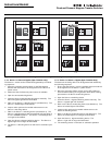
4. Inspect and/or perform the needed maintenance on the Source
1 switching device.
5. Rack in the Source 1 switching device (see Section 6). The
Source 1 switching device will automatically recharge and
close when it is in the CONNECT position. The Source 1 iso-
lated light will no longer be illuminated, but the Source 1 posi-
tion energized light will be illuminated.
6. Open the Source 1 bypass switch. The Source 1 bypassed
light will no longer be illuminated.
7. The Source 1 switching device is now back in automatic oper-
ation.
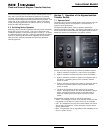
7.3.2 Source 2 TO Source 2 BYPASS
The Source 2 switching device can be bypassed and isolated by
the following sequence:
1. Move the generator selector switch to the RUN position to
avoid losing power.
2. Close the Source 2 bypass switching device manually. The
Source 2 bypass light will illuminate.
3. Open and rack out the Source 2 switching device
(see Section 6). The Source 2 isolated light will illuminate and
the Source 2 position energized light will no longer be illumi-
nated.
4. Inspect and/or perform the needed maintenance on the Source
2 switching device.
5. Rack in the Source 2 switching device (see Section 6). The
Source 2 switching device will automatically recharge and
close when in the CONNECT position. The Source 2 isolated
light will no longer be illuminated, and the Source 2 position
energized light will illuminate.
6. Open the Source 2 Bypass switch. The source 2 Bypass light
will no longer be illuminated.
7. The Source 2 Switch is now back in automatic operation.
WARNING
THE CLOSED TRANSITION PRODUCT CONTAINS A SPECIAL CON-
TACT ARRANGEMENT (OVERLAPPING CONTACTS). MISUSE CAN
RESULT IN DEATH, SEVERE PERSONAL INJURY, AND/OR PROPERTY
DAMAGE.