


IB01602011E For more information visit: www.Eaton.com
Instructional Booklet
Effective: March 2007 Page 3
Fixed and Drawout Magnum Transfer Switches
Section 1: Introduction
1.1 Preliminary Comments and Safety Precautions
This technical document is intended to cover most aspects associ-
ated with the installation, application, operation, and maintenance
of transfer switch equipment with ratings from 800 through
3200 amperes (A), except for the specific logic used to control
the equipment. It is provided as a guide for authorized and quali-
fied personnel only. Please refer to the specific WARNING and
CAUTION in Section 1.1.2 before proceeding. If further informa-
tion is required by the purchaser regarding a particular installation,
application, or maintenance activity, contact an Eaton representa-
tive. For information associated with the control, refer to the sep-
arate instruction book pertaining to the logic package installed in
the switch.
1.1.1 Warranty and Liability Information
No warranties, expressed or implied, including warranties of fit-
ness for a particular purpose of merchant-ability, or warranties
arising from course of dealing or usage of trade, are made regard-
ing the information, recommendations and descriptions contained
herein. In no event will Eaton be responsible to the purchaser or
user in contract, in tort (including negligence), strict liability or
otherwise for any special, indirect, incidental or consequential
damage or loss whatsoever, including but not limited to damage or
loss of use of equipment, plant or power system, cost of capital,
loss of power, additional expenses in the use of existing power
facilities, or claims against the purchaser or user by its customers
resulting from the use of the information and descriptions con-
tained herein.
1.1.2 Safety Precautions
All safety codes, safety standards, and/or regulations must be
strictly observed in the installation, operation, and maintenance of
this device.
.
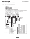
1.2 General Information
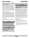
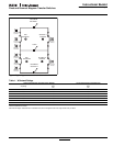
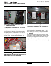
Transfer switches are used to protect critical electrical loads
against loss of power. The Source 1 power source of the load is
backed-up by a Source 2 power source. A transfer switch is con-
nected to both the Source 1 and Source 2 power sources and sup-
plies the load with power from one of these two sources. In the
event that power is lost from the Source 1 power source, the
transfer switch transfers the load to the Source 2 power source.
This transfer can be automatic or manual, depending upon the
type of transfer switch equipment being used. Once Source 1
power is restored, the load is automatically or manually trans-
ferred back to the Source 1 power source, again depending upon
the type of transfer equipment being used (Figure 2).
In addition, the Eaton closed transition transfer switch may be
applied where it is desirable to avoid any momentary power inter-
ruptions. Although the closed transition switch is not a substitute
for an uninteruptable power source (UPS), it does eliminate power
interruptions to loads except to those caused by power sources or
equipment external to the transfer switch. If both sources are
acceptable as determined by the IQ Transfer logic, a make-before-
break transfer is performed during a transfer test or retransfer
operation.
1.2.1 Transfer Switch Types
There are four types of transfer switch equipment.
Automatic Transfer Switch
Automatic transfer switches (ATSs) automatically perform the
transfer function. They consist of three basic elements:
1. Main contacts to connect and disconnect the load to and from
the source of power.
2. Intelligence/supervisory circuits to constantly monitor the con-
dition of the power sources and thus provide the intelligence
necessary for the switch and related circuit operation.
3. A transfer mechanism to effect the transfer of the main con-
tacts from source to source.
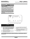
WARNING
THE WARNINGS AND CAUTIONS INCLUDED AS PART OF THE PRO-
CEDURAL STEPS IN THIS DOCUMENT ARE FOR PERSONNEL SAFETY
AND PROTECTION OF EQUIPMENT FROM DAMAGE. AN EXAMPLE
OF A TYPICAL WARNING LABEL HEADING IS SHOWN ABOVE TO
FAMILIARIZE PERSONNEL WITH THE STYLE OF PRESENTATION.
THIS WILL HELP TO INSURE THAT PERSONNEL ARE ALERT TO
WARNINGS, WHICH APPEAR THROUGHOUT THE DOCUMENT. IN
ADDITION, CAUTIONS ARE ALL UPPER CASE AND BOLDFACE.
CAUTION
COMPLETELY READ AND UNDERSTAND THE MATERIAL PRESENTED
IN THIS DOCUMENT BEFORE ATTEMPTING INSTALLATION, OPERA-
TION, OR APPLICATION OF THE EQUIPMENT. IN ADDITION, ONLY
QUALIFIED PERSONS SHOULD BE PERMITTED TO PERFORM ANY
WORK ASSOCIATED WITH THE EQUIPMENT. ANY WIRING
INSTRUCTIONS PRESENTED IN THIS DOCUMENT MUST BE FOL-
LOWED PRECISELY. FAILURE TO DO SO COULD CAUSE PERMA-
NENT EQUIPMENT DAMAGE.
WARNING
THE CLOSED TRANSITION PRODUCT CONTAINS A SPECIAL CON-
TACT ARRANGEMENT (OVERLAPPING CONTACTS). MISUSE CAN
RESULT IN DEATH, SEVERE PERSONAL INJURY, AND/OR PROPERTY
DAMAGE.