


For more information visit: www.Eaton.com IB01602011E
Instructional Booklet
Page 2 Effective: March 2007
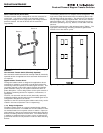
Fixed and Drawout Magnum Transfer Switches
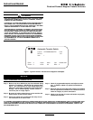
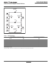
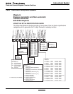
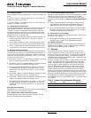
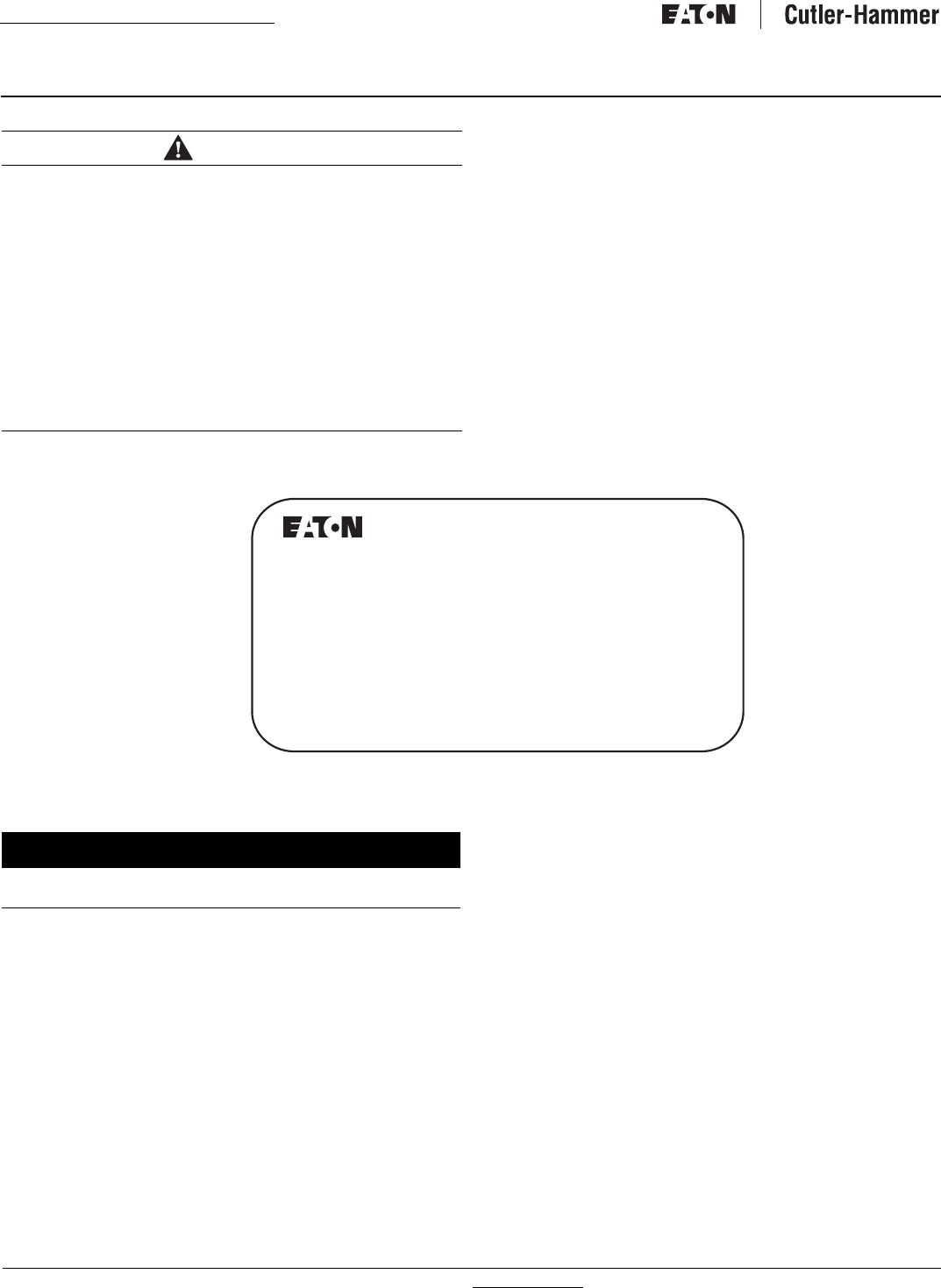
Figure 1. Typical Automatic Transfer Switch Equipment Nameplate.
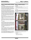
Step 1: Remove any dirt or debris that may have collected during
shipment or installation. NEVER use high pressure blow-
ing air. This could drive dirt or other foreign objects into
electrical or mechanical components which could cause
damage. Use an industrial quality vacuum cleaner to
remove any dirt or foreign objects.
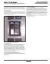
Step 2: Be certain all cable connections are correct and that the
phase rotation of both sources match.
Step 3: Inspect the engine start connections and verify the cor-
rect connection of all control wires.
Step 4: Check all programmable setpoints and adjust as neces-
sary. In addition, adjust any optional accessories as
required.
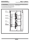
Step 5: Be certain that the actual lug torque values are in keeping
with the requirements outlined in the instruction book to
insure the integrity of power connections.
Step 6: Check to be sure that all covers and barriers are properly
installed and fastened.
ALL POSSIBLE CONTINGENCIES WHICH MAY ARISE DURING INSTALLATION, OPERATION, OR MAINTENANCE, AND ALL DETAILS AND VARIA-
TIONS OF THIS EQUIPMENT DO NOT PURPORT TO BE COVERED BY THESE INSTRUCTIONS. IF FURTHER INFORMATION IS DESIRED BY THE
PURCHASER REGARDING HIS PARTICULAR INSTALLATION, OPERATION, OR MAINTENANCE OF PARTICULAR EQUIPMENT, CONTACT AN
EATON REPRESENTATIVE.
WARNING
READ AND UNDERSTAND THE INSTRUCTIONS CONTAINED HEREIN-
AFTER BEFORE ATTEMPTING TO UNPACK, ASSEMBLE, OPERATE,
OR MAINTAIN THIS EQUIPMENT.
HAZARDOUS VOLTAGES ARE PRESENT INSIDE TRANSFER SWITCH
ENCLOSURES THAT CAN CAUSE DEATH OR SEVERE PERSONAL
INJURY. FOLLOW PROPER INSTALLATION, OPERATION, AND MAIN-
TENANCE PROCEDURES TO AVOID THESE VOLTAGES.
TRANSFER SWITCH EQUIPMENT COVERED BY THIS INSTRUCTION
BOOK IS DESIGNED AND TESTED TO OPERATE WITHIN ITS NAME-
PLATE RATINGS. OPERATION OUTSIDE OF THESE RATINGS MAY
CAUSE THE EQUIPMENT TO FAIL RESULTING IN DEATH, SERIOUS
BODILY INJURY, AND/OR PROPERTY DAMAGE. ALL RESPONSIBLE
PERSONNEL SHOULD LOCATE THE DOOR MOUNTED EQUIPMENT
NAMEPLATE AND BE FAMILIAR WITH THE INFORMATION PROVIDED
ON THE NAMEPLATE. A TYPICAL EQUIPMENT NAMEPLATE IS
SHOWN IN FIGURE 1.
NOTICE
A FINAL INSPECTION OF THE EQUIPMENT SHOULD BE PERFORMED
PRIOR TO ENERGIZING THE TRANSFER SWITCH.
E
Automatic Transfer Switch
Cat No: ATVIMGB33200XRU 11/04
GO No: 1of1
Item 1
Poles: 3 Amps: 3200 Volt: 120/600 VAC
Phase: 3 Hertz: 60 Wire: 4