


For more information visit: www.Eaton.com IB01602011E
Instructional Booklet
Page 10 Effective: March 2007
Fixed and Drawout Magnum Transfer Switches
Section 2: Receiving, Handling, and Storage
2.1 Receiving
Every effort is made to ensure that the transfer switch equipment
arrives at its destination undamaged and ready for installation.
Crating and packing is designed to protect internal components as
well as the enclosure. Transfer switch enclosures are skid
mounted and suited for fork lift movement. Care should be exer-
cised, however, to protect the equipment from impact at all times.
Do not remove the protective packaging until the equipment is at
the installation location and ready for installation.
When the transfer switch equipment reaches its destination, the
customer should inspect the shipping container for any obvious
signs of rough handling and/or external damage incurred during
transportation. Record any external and internal damage observed
for reporting to the transportation carrier and Eaton, once a thor-
ough inspection is completed. All claims should be as specific as
possible and include the Shop Order and General Order numbers.
A shipping label is affixed to the top of the shipping container
which includes a variety of equipment and customer information,
such as General Order Number (GO #) and Catalog Number
(Cat #). Make certain that this information matches other ship-
ping paper information.
Each transfer switch enclosure is bolted to a rigid wooden pallet.
The pallet is open at two ends for movement by a fork lift. The
shipment is secured and further protected with shrink wrap. Do
not discard the packing material until the equipment is ready for
installation.
A plastic bag of documents will be found within the enclosure,
usually attached to the inside of the door. Important documents,
such as test reports, wiring diagrams, and appropriate instruction
leaflets, are enclosed within the bag and should be filed in a safe
place.
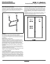
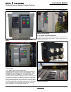
2.2 Handling
As previously mentioned, the transfer switch equipment is pack-
aged for fork lift movement. Protect the equipment from impact
at all times and DO NOT double stack. Once the equipment is at
the installation location and ready for installation, the packaging
material can be removed. Once the enclosure is unbolted from the
wooden pallet, it can be installed using the lifting provision located
on the top of the structure. Be careful not to damage the top or
bottom enclosure mounting flanges. Refer to Section 4 of this
manual for specific installation instructions.
2.3 Storage
Although well packaged, this equipment is not suitable for storage
outdoors. The equipment warranty will not be applicable if there
is evidence of outdoor storage. If the equipment is to be stored
indoors for any period of time, it should be stored with its protec-
tive packaging material in place. Protect the equipment at all
times from excessive moisture, construction dirt, corrosive condi-
tions, and other contaminants.
It is strongly suggested that the package-protected equipment be
stored in a climate controlled environment of -20° to 85°C
(-4° to 185°F) with a relative humidity of 80% or less. DO NOT,
under any circumstances, stack other equipment on top of a trans-
fer switch equipment enclosure, whether packaged or not.
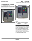
Section 3: Equipment Description
3.1 General
This Eaton transfer switch equipment is available in four different
configurations:
• ATS (Closed and Open transition);
• Non-Automatic (Electrically Operated) (Open Transition Only);
• Bypass Isolation Transfer Switch (Open and Closed Transition);
and
• Power Panel.
Refer to Section 1 for a discussion of all four types. Each transfer
switch is usually supplied in an enclosure, although unmounted
sub-assemblies can be supplied for mounting by the customer.
The enclosed ATS is the only specific type that will be discussed
in this section.
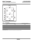
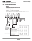
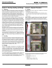
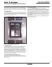
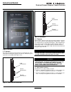
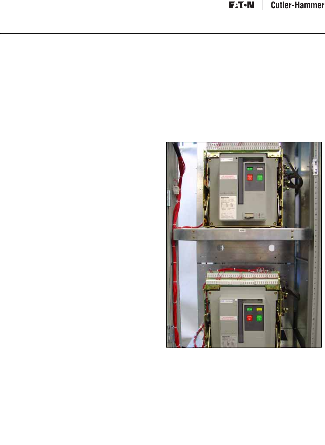
Figure 11. Typical Power Panel (Open Transition Shown).
The enclosed ATS consists of three basic panels interconnected
through connector plugs and mounted in an enclosure:
• Power Panel;
• Voltage Selection Panel; and
• Logic Panel
•
ATC-600 (open transition only)
•
ATC-800 (closed transition only).