


IB01602011E For more information visit: www.Eaton.com
Instructional Booklet
Effective: March 2007 Page 19
Fixed and Drawout Magnum Transfer Switches
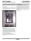
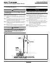
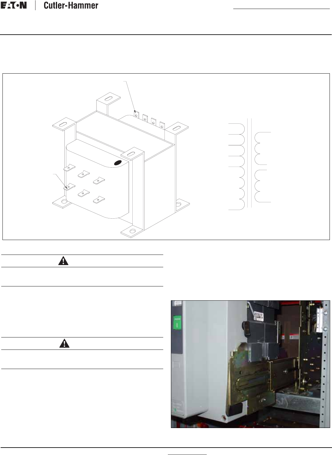
4.6 Voltage Selection Adjustment
Certain devices, such as the voltage selection panel, sensing
relays, and timers need to be set and/or calibrated prior to placing
the transfer switch equipment into service. Adjustments for logic
devices are described in the separate instructional document dedi-
cated to the specific logic being used. Voltage selection adjust-
ments are described here
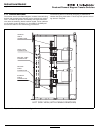
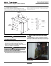
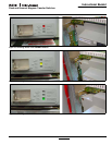
Figure 21. Voltage Selection Adjustment.
• Remove the transformer pack cover by loosening the 4 screws
located at each corner of the transformer pack assembly.
• The transformers are factory set on the 600 volt tap. (See illus-
tration above for location of various taps and voltages)
• Detach the spade connector from the 600 volt tap and place on
the tap that is suitable for your application.
.
• After changing the taps on both transformers, replace the trans-
former pack cover and tighten all four screws.
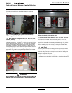
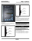
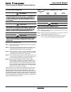
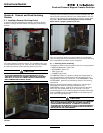
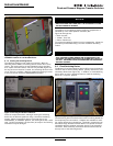
4.7 Mounting the Switching Device in the Drawout
Mechanism
In structures equipped for drawout circuit breakers, a bolted-in
cassette with movable extension rails supports the circuit breaker
(Figure 22). The extension rails must first be pulled all the way
out. Once the rails are fully extended, the circuit breaker can be
carefully placed on the extension rails.
Figure 22. One Side of Drawout Circuit Breaker Properly Seated
on Extension Rails.
PRIMARY
TERMINALS
SECONDARY
TERMINALS
600V 6
480V 5
240V 4
208V 3
120V 2
0V 1
60Hz
7
8
9
10
SECONDARY 1
120V, 300VA
INTERMITTENT 50%
DUTY CYCLE
SECONDARY 2
120V, 25VA
5
10
9
8
7
120V. 1.5A
7
8
10
9
120V 0.21A
TOP: 5-480V 3-208V
1-COMMON
BOTTOM: 6-600V 4-240V 2-12
0V
3
1
6
4
2
WARNING
DISCONNECT ALL SOURCES OF POWER OR DISCONNECT P7/S7
PRIOR TO PERFORMING THE FOLLOWING. FAILURE TO DO SO MAY
CAUSE SERIOUS INJURY OR DEATH.
CAUTION
BE SURE THAT THE CORRECT VOLTAGE IS SELECTED TO MATCH
THE SYSTEM VOLTAGE. AN IMPROPER SELECTION AND/OR CON-
NECTION COULD RESULT IN EQUIPMENT DAMAGE.