


IB01602011E For more information visit: www.Eaton.com
Instructional Booklet
Effective: March 2007 Page 13
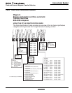
Fixed and Drawout Magnum Transfer Switches
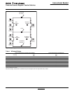
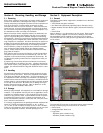
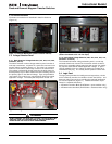
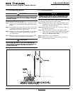
3.2.5 Drawout Mechanism
The drawout mechanism is described in detail in Section 6
(Figure 14).
Figure 14. Drawout Mechanism (Closed Transition Shown)
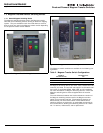
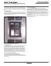
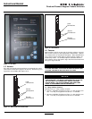
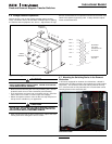
3.3 Voltage Selection Panel
3.3.1 North American Voltage Selection (120, 208, 240, 480,
and 600 V, 60 Hz)
The North American market voltage selection panel consists of
multi-tap transformers, contained in a steel case mounted in the
transfer switch enclosure (Figure 15). The cover has “teardrop”
holes for the screws to allow easy access to the transformers.
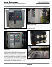
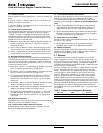
The voltage is selected by simply removing the wires from the
default primary taps of both transformers and installing them on
the primary taps for the desired voltage. Taps are provided for
120 to 600 Vac to satisfy any required North American market
application voltage. The factory default position is 600 Vac.
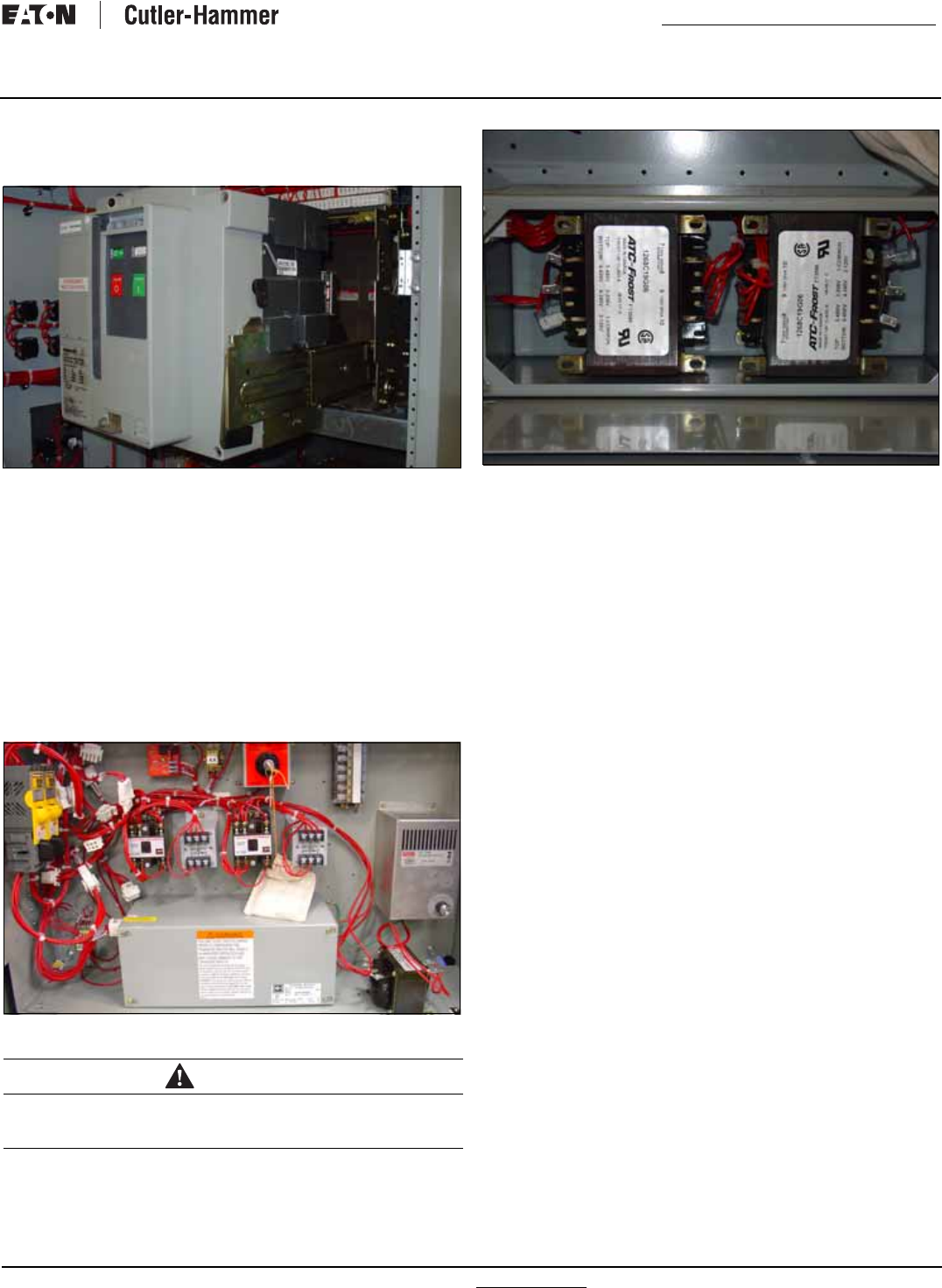
Figure 15. Voltage Selection Panel
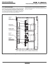
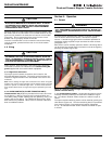
Figure 16. North American Market Voltage Selection Terminals
(Shown Connected to the 120 Vac Taps).
3.3.2 International Voltage Selection (208, 220, 240, 380, 415,
and 600 V 50-60 Hz).
The international market voltage selection panel is a multi-tap,
enclosed transformer mounted in the transfer switch enclosure.
Seven front accessible voltage taps from 208 to 600 Vac satisfy
any required international market application voltage. A quick-
change capability from one voltage to another is provided by a
small disconnect plug. The factory default position is 600 VAC.
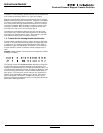
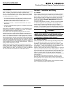
3.4 Logic Panel
The logic panel provides the intelligence and supervisory circuits
which constantly monitor the condition of both the Source 1 and
Source 2 power sources, thus providing the required intelligence
for transfer operations (Figure 17). Detailed information is pre-
sented in a separate document:
• ATC-600 Instruction Book (IB ATS-I005 - open transition only)
• ATC-800 Instruction Book (IB ATS-CI03 - closed transition only)
WARNING
WHEN CHANGING THE SELECTED VOLTAGE, THE POWER MUST BE
REMOVED FROM THE TRANSFER SWITCH AND THE WIRES MUST
BE MOVED ON THE TAPS OF BOTH TRANSFORMERS.