


IB01602011E For more information visit: www.Eaton.com
Instructional Booklet
Effective: March 2007 Page 29
Fixed and Drawout Magnum Transfer Switches
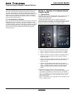
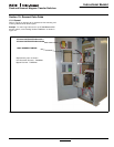
7.4 Manual Operation When in Bypass Mode
7.4.1 Source 1 Bypass to Source 2 Bypass
When the transfer switch is set to Source 1 bypass, it can be
transferred to Source 2 bypass by the following sequence:
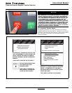
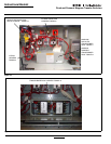
1. Move the generator selector switch to the RUN position.
2. Open the Source 1 bypass switching device. The Source 1
bypass light will no longer be illuminated.
3. Close the Source 2 bypass switching device manually and the
Source 2 bypass light will illuminate.
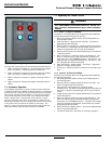
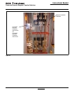
7.4.2 Source 2 Bypass to Source 1 Bypass
When the transfer switch is set to Source 2 bypass, it can be
transferred to the Source 1 bypass switching device by the follow-
ing sequence:
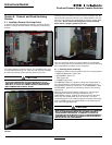
1. Open the Source 2 bypass switching device and the Source 2
bypass light will no longer be illuminated.
2. Close the Source 1 bypass switching device manually and the
Source 1 bypass light will illuminate.
3. Move the generator selector switch to the OFF position.
Section 8: Testing and Problem Solving
8.1 Testing
After transfer switch equipment is initially installed or during
planned outages, the installation should be tested to ensure that all
equipment operates properly. This attention to detail will help to
avoid unexpected malfunctions. Mechanical and/or electrical tests
should be performed.
The frequency of subsequent testing should be based on recom-
mendations of the generator set manufacturer. Use the test push-
button to check the electrical operation of the switch. IF A TEST
SWITCH IS PROVIDED, ALWAYS RETURN THE SWITCH TO THE
AUTO POSITION AFTER THE TEST IS COMPLETE.
8.2 Problem Solving
A basic problem solving effort is the first step to take prior to call-
ing for assistance. Frequently, the effort will successfully address
most problems encountered. Most problem solving procedures
are outlined in the instruction manual unique to the type of logic
being used. In addition, several problem solving procedures are
presented here which are specific to the type of switches or
switching devices used in this equipment.
WARNING
HIGH VOLTAGES ASSOCIATED WITH OPERATIONAL TRANSFER
SWITCH EQUIPMENT PRESENT A SHOCK HAZARD THAT CAN
CAUSE SEVERE PERSONAL INJURY OR DEATH. USE EXTREME
CAUTION TO AVOID TOUCHING ELECTRICAL CONNECTIONS
WHENEVER INSPECTING OR TESTING THE EQUIPMENT.
IN ADDITION, IMPROPER OPERATION OF THE GENERATOR SET PRE-
SENTS A HAZARD THAT CAN CAUSE SEVERE PERSONAL INJURY
OR DEATH. OBSERVE ALL SAFETY PRECAUTIONS IN YOUR GENER-
ATOR SET OPERATIONS AND INSTALLATION MANUALS
WARNING
FOR MECHANICAL OPERATIONS, REFER TO SECTION 5. IN THIS
INSTRUCTION BOOK. REFER TO THE APPLICABLE LOGIC INSTRUC-
TION BOOK FOR ELECTRICAL TESTING
WARNING
HAZARDOUS VOLTAGES IN AND AROUND TRANSFER SWITCH
EQUIPMENT DURING THE PROBLEM SOLVING PROCESS CAN
CAUSE PERSONAL INJURY AND/OR DEATH. AVOID CONTACT
WITH ANY VOLTAGE SOURCE WHILE PROBLEM SOLVING.
WARNING
ONLY PROPERLY TRAINED PERSONNEL FAMILIAR WITH THE
TRANSFER SWITCH EQUIPMENT AND ITS ASSOCIATED EQUIP-
MENT SHOULD BE PERMITTED TO PERFORM THE PROBLEM SOLV-
ING FUNCTION. IF AN INDIVIDUAL DOES NOT FEEL QUALIFIED TO
PERFORM THE PROBLEM SOLVING FUNCTION, THE INDIVIDUAL
SHOULD NOT ATTEMPT TO PERFORM ANY OF THESE PROCE-
DURES.