


Chapter 3 Installing Optional SSMs
What to Do Next
3-10
Cisco ASA 5500 Series Adaptive Security Appliance Getting Started Guide
78-17611-01
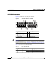
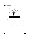
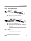
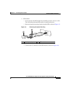
Figure 3-6 Removing the Screws from the Slot Cover
Step 4
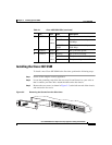
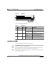
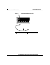
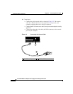
Insert the SSM into the slot opening as shown in Figure 3-7.
Figure 3-7 Inserting the SSM into the Slot
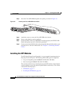
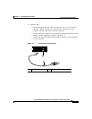
Step 5 Attach the screws to secure the SSM to the chassis.
Step 6 Power on the adaptive security appliance. Check the LEDs. If the SSM is installed
properly the POWER LED is solid green and the STATUS LED flashes green.
Step 7 Connect one end of the RJ-45 cable to the port and the other end of the cable to your
network devices.
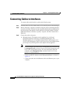
What to Do Next
Continue with Chapter 4, “Connecting Interface Cables.”
119642
LINK SPD
3
LINK SPD
2
LINK SPD
1
LINK SPD
0
MGMT
USB2
USB1
FLASH
POWER
STATUS
F
L
A
S
H
VPN
ACTIVE
119643
PWR
STATUS
SPEED
LINK/ACT
LINK SPD
3
LINK SPD
2
LINK SPD
1
LINK SPD
0
MGMT
USB2
USB1
POWER
STATUS
FLASH
VPN
ACTIVE