


Chapter 3 Installing Optional SSMs
Cisco 4GE SSM
3-4
Cisco ASA 5500 Series Adaptive Security Appliance Getting Started Guide
78-17611-01
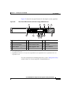
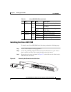
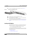
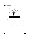
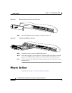
Step 4 Insert the Cisco 4GE SSM through the slot opening as shown in Figure 3-3.
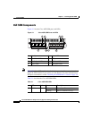
Figure 3-3 Inserting the Cisco 4GE SSM into the Slot
Step 5
Attach the screws to secure the Cisco 4GE SSM to the chassis.
Step 6 Power on the adaptive security appliance.
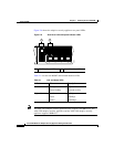
Step 7 Check the LEDs. If the Cisco 4GE SSM is installed properly the STATUS LED
flashes during boot up and is solid when operational.
Step 8 Connect one end of the RJ-45 cable to the port and the other end of the cable to your
network devices. For more information, see “Chapter 4, “Connecting Interface
Cables.”
Installing the SFP Modules
The SFP (Small Form-Factor Pluggable) is a hot-swappable input/output device
that plugs into the SFP ports. The following SFP module types are supported:
• Long wavelength/long haul 1000BASE-LX/LH (GLC-LH-SM=)
• Short wavelength 1000BASE-SX (GLC-SX-MM=)
This section describes how to install and remove the SFP modules in the adaptive
security appliance to provide optical Gigabit Ethernet connectivity. This section
contains the following topics:
• SFP Module, page 3-5
• Installing the SFP Module, page 3-6
132984
MGMT
USB2
USB1
POWER
S
T
A
T
U
S
C
isco
S
SM
-4G
E
LNK
SPD0
1
23
L
IN
K
S
P
D
3
L
IN
K
S
P
D
2
L
IN
K
S
P
D
1
L
IN
K
S
P
D
0
F
LA
S
H
PO
W
ER
STAT U
S
FLASH
VPN
ACTIVE
MGMT
USB2
USB1