


Chapter 11 Configuring the 4GE SSM for Fiber
Cabling 4GE SSM Interfaces
11-2
Cisco ASA 5500 Series Adaptive Security Appliance Getting Started Guide
78-17611-01
Cabling 4GE SSM Interfaces
To cable 4GE SSM interfaces, perform the following steps for each port you want
to connect to a network device:
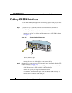
Step 1 To connect an RJ-45 (Ethernet) interface to a network device, perform the
following steps for each interface:
a. Locate a yellow Ethernet cable from the accessory kit.
b. Connect one end of the cable to an Ethernet port on the 4GE SSM as shown
in Figure 11-1.
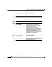
Figure 11-1 Connecting the Ethernet port
c.
Connect the other end of the cable to your network device.
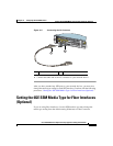
Step 2 (Optional) If you want to use an SFP (fiber optic) port, install and cable the SFP
modules as shown in Figure 11-2:
a. Insert and slide the SFP module into the SFP port until you hear a click. The
click indicates that the SFP module is locked into the port.
b. Remove the optical port plugs from the installed SFP.
c. Locate the LC connector (fiber optic cable) in the 4GE SSM accessory kit.
d. Connect the LC connector to the SFP port.
1 RJ-45 (Ethernet) port
143597
MGMT
USB2
Cisco SSM-4GE
LNK
SPD
0
1
2
3
POW
ER
STATUS
MGMT
USB2
USB1
Cisco SSM-4GE
1