


2-7
Cisco ASA 5500 Series Adaptive Security Appliance Getting Started Guide
78-17611-01
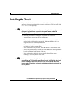
Chapter 2 Installing the Cisco ASA 5500
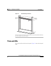
Ports and LEDs
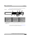
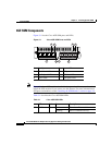
Figure 2-5 shows the rear panel features for the adaptive security appliance.
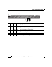
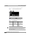
Figure 2-5 Rear Panel LEDs and Ports (AC Power Supply Model Shown)
For more information on the Management Port, see the “Management-Only”
section in the Cisco Security Appliance Command Reference.
1 Management Port
1
1. The management 0/0 interface is a Fast Ethernet interface designed for management traffic only.
6 USB 2.0 interfaces
2
2. Not supported at this time.
11 VPN LED
2 External CompactFlash slot 7 Network interfaces
3
3. GigabiteEthernet interfaces, from right to left, GigabitEthernet 0/0, GigabitEthernet 0/1, GigabitEthernet 0/2, and
GigabitEthernet 0/3.
12 Flash LED
3 Serial Console port 8 Power indicator LED 13 AUX port
4 Power switch 9 Status indicator LED 14 Power connector
5 Power indicator LED 10 Active LED
119572
LINK SPD
3
LINK SPD
2
LINK SPD
1
LINK SPD
0
MGMT
USB2
USB1
FLASH
CONSOLE
AUX
POWER
STATUS
FLASH
1
9
2
3
4
5
11
13
14
7
6
8 10 12
VPN
ACTIVE