


3-9
Cisco ASA 5500 Series Adaptive Security Appliance Getting Started Guide
78-17611-01
Chapter 3 Installing Optional SSMs
Cisco AIP SSM and CSC SSM
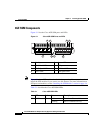
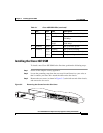
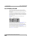
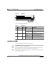
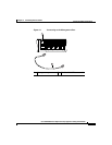
Figure 3-5 SSM LEDs
Table 3-5 describes the SSM LEDs.
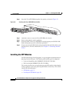
Installing an SSM
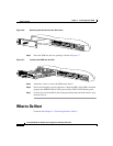
To install a new SSM, perform the following steps:
Step 1 Power off the adaptive security appliance.
Step 2 Locate the grounding strap from the accessory kit and fasten it to your wrist so
that it contacts your bare skin. Attach the other end to the chassis.
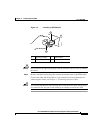
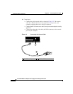
Step 3 Remove the two screws (as shown in Figure 3-6) at the left rear end of the chassis,
and remove the slot cover.
119644
PWR
STATUS
SPEED
LINK/ACT
1 2
3 4
Table 3-5 SSM LEDs
LED Color State Description
1 PWR Green On The system has power.
2 STATUS Green Flashing The system is booting.
Solid The system has passed power-up
diagnostics.
3 LINK/ACT Green Solid There is an Ethernet link.
Flashing There is Ethernet activity.
4 SPEED Green
Amber
100 MB There is network activity.
1000 MB (GigE) There is network activity.