


2-7
Installation Guide for the Cisco Secure PIX Firewall Version 5.2
78-11180-01
Chapter 2 Installing a PIX Firewall
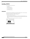
Installing a PIX 515
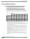
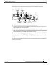
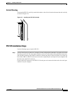
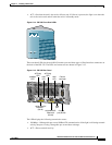
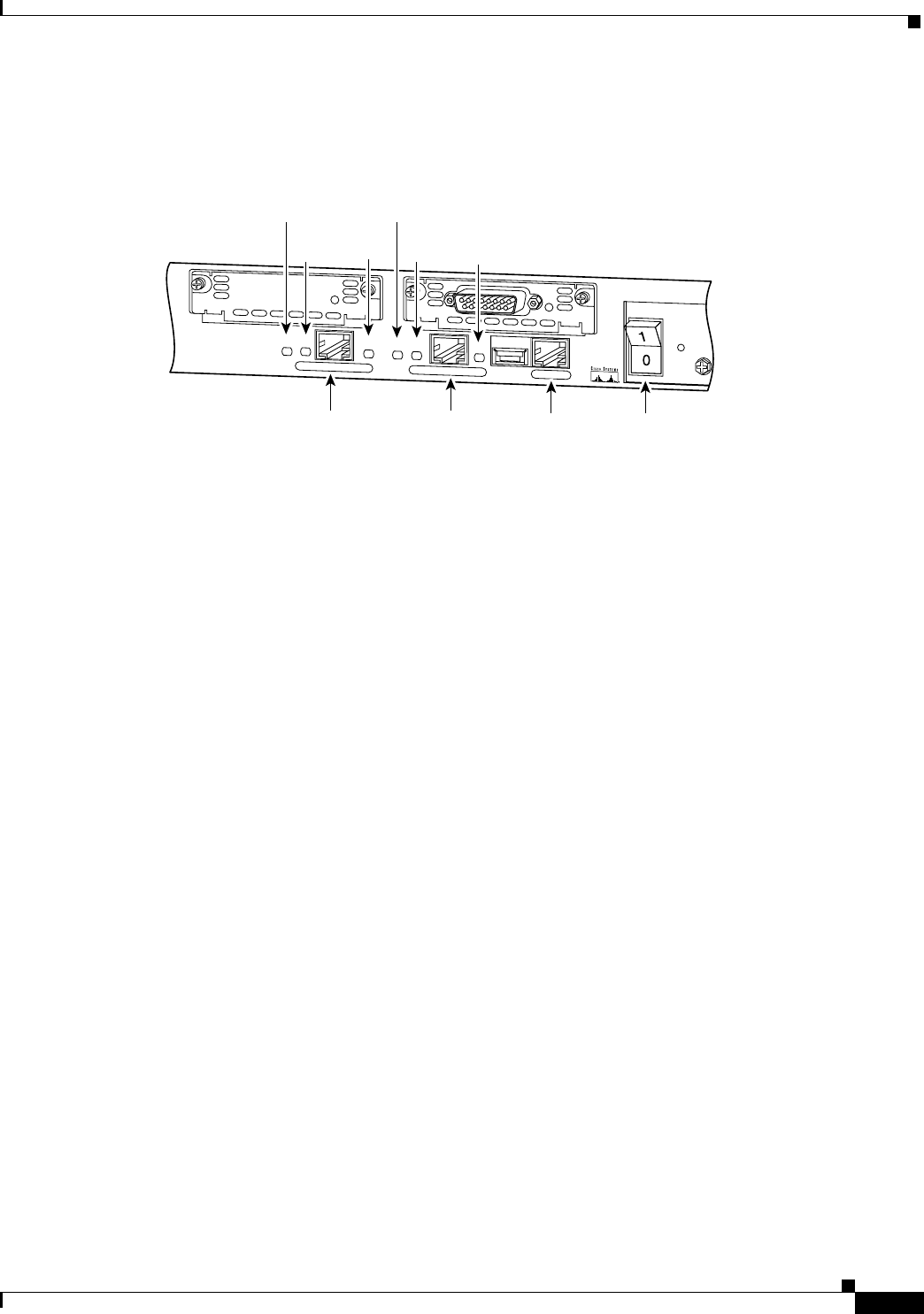
Refer to Figure 2-6 for a display of the controls and connectors on the PIX 515 back panel.
Figure 2-6 PIX 515 Features
The LEDs for the network ports display the following transmission states:
• 100 Mbps—100 megabits per second 100BaseTX communication. If the light is off, that port is
using 10 megabits per second data exchange.
• LINK—Shows that data is passing on the network to which the connector is attached.
• FDX—Shows that the connection uses full-duplex data exchange where data can be transmitted and
received simultaneously. If this light is off, half-duplex is in effect.
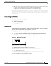
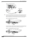
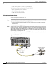
The inside or outside network connections can be made to any available interface port on the PIX 515.
If you are only using the ETHERNET 0 and ETHERNET 1 ports, connect the inside network cable to
the interface connector marked ETHERNET 0 or ETHERNET 1. Connect the outside network cable to
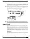
the remaining Ethernet port. Refer to “Configuring the PIX 515” for information on how to configure
the ports.
The USB port to the left of the Console port is not used. The detachable plate above the ETHERNET 1
connector is also not used.
24298
DO NOT INSTALL INTERFACE
CARDS WITH POWER APPLIED
CONSOLE
10/100 ETHERNET 0
Link
FDX
FDX
100 Mbps
Link
100 Mbps
FAILOVER
10/100 ETHERNET 1
PIX-515
10/100BaseTX
ETHERNET 0
(RJ-45)
10/100BaseTX
ETHERNET 1
(RJ-45)
Console
port (RJ-45)
Power switch
FDX
LED
FDX
LED
LINK
LED
100 Mbps
LED
LINK
LED
100 Mbps
LED