2-20
Installation Guide for the Cisco Secure PIX Firewall Version 5.2
78-11180-01
Chapter 2 Installing a PIX Firewall
Installing a PIX 520 or Earlier Model
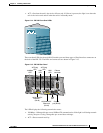
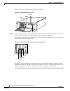
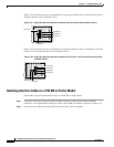
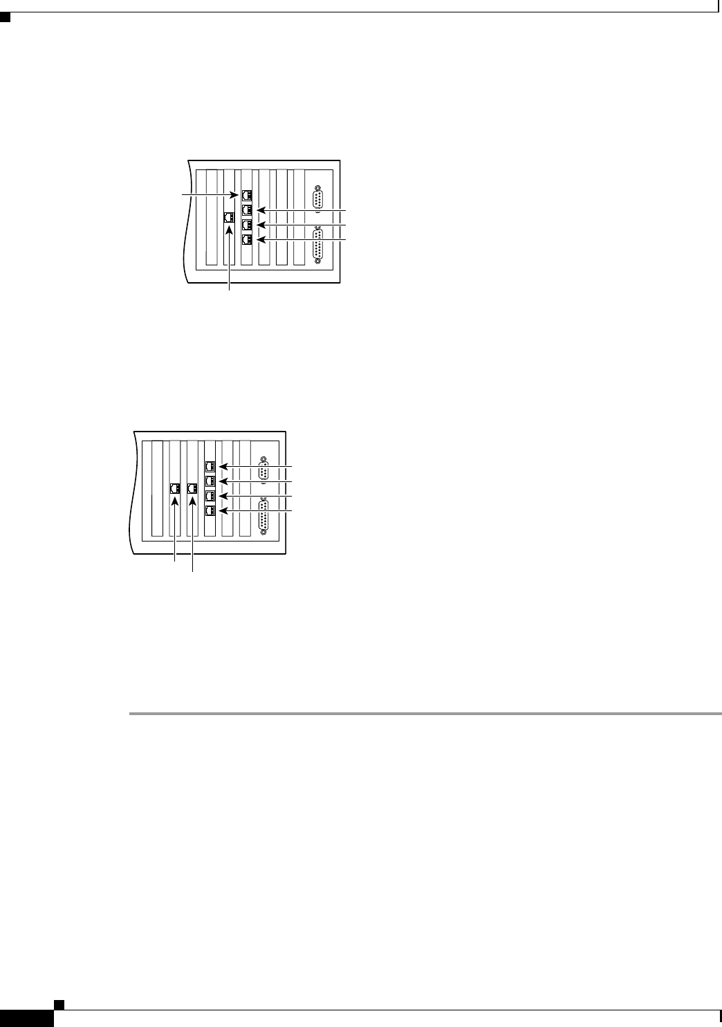
Figure 2-21 shows how the slots are numbered if a single-port interface card is inserted in slot 0 and a
four-port interface card is inserted in slot 1.
Figure 2-21 Single-Port Ethernet Interface Installed in Slot 0 and Four-Port Installed in Slot 1
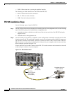
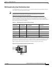
Figure 2-22 shows how the slots are numbered if single-port interface cards are installed in slot 0 and
in slot 1 and a four-port interface card is inserted in slot 2.
Figure 2-22 Single-Port Ethernet Interface Installed in Slot 0 and 1 and Four-Port Ethernet Interface
Installed in Slot 2
Installing Interface Cables to a PIX 520 or Earlier Model
Follow these steps to install interface cables to a PIX 520 or earlier model:
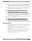
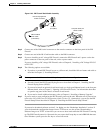
Step 1 Locate the serial cable. The serial cable assembly consists of a null modem cable with RJ-45
connectors, two separate DB-9 connectors, and a separate DB-25 connector as shown in Figure 2-23.
Step 2 Install the serial cable between the PIX Firewall and your console computer.
44307
Interface 0
Interface 1
Interface 2
Interface 3
Interface 4
44308
Interface 0
Interface 1
Interface 3
Interface 4
Interface 2
Interface 5


