


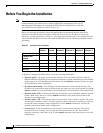
2-10
Installation Guide for the Cisco Secure PIX Firewall Version 5.2
78-11180-01
Chapter 2 Installing a PIX Firewall
Installing a PIX 515
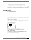
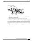
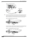
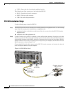
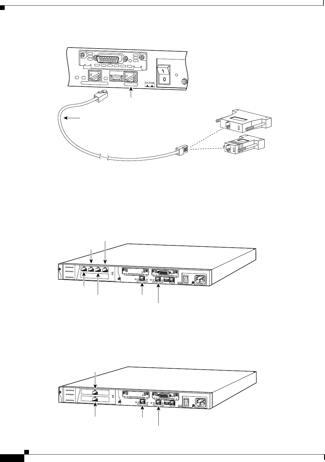
Figure 2-9 PIX 515 Serial Console Cable
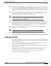
Step 2
If your unit has a four-port Ethernet card already installed, refer to Figure 2-10. (The four-port interface
card requires the PIX-515-UR license to be accessed.) If it has one or two single-port cards, refer to
Figure 2-11. If you need to install an optional circuit board such as a Private Link board, single-port
Ethernet board, FDDI board, or a four-port Ethernet board, refer to Chapter 5, “Opening a PIX Firewall
Chassis” for information about how to open the top panel of the chassis to install circuit boards.
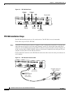
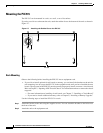
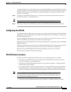
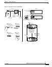
Figure 2-10 Four-Port Ethernet Connectors in a PIX 515
Connect the inside, outside, or perimeter network cables to the interface ports. Starting from the top left
the connectors are Ethernet 2, Ethernet 3, Ethernet 4, and Ethernet 5. The maximum number of allowed
interfaces is 6; do not add a single-port card in the extra slot below the four-port card.
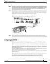
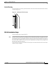
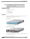
Figure 2-11 Two Single-Port Ethernet Connectors in a PIX 515
CONSOLE
10/100 ETHERNET 0
FDX
Link
100 Mbps
FAILOVER
PIX-515
Console
port (RJ-45)
29226
RJ-45 to
DB-9 or DB-25
serial cable
(null-modem)
Computer serial port
DB-9 or DB-25
D
O
N
O
T
IN
S
T
A
L
L
IN
T
E
R
F
A
C
E
C
A
R
D
S
W
IT
H
P
O
W
E
R
A
P
P
L
IE
D
C
O
N
S
O
LE
10/100 E
T
H
ER
N
E
T
0
L
in
k
F
D
X
F
D
X
1
0
0
M
b
p
s
L
in
k
1
0
0
M
b
p
s
F
A
IL
O
V
E
R
10/1
0
0 E
TH
E
R
NE
T
1
PIX-515
25733
Ethernet 2
Ethernet 4
Ethernet 1
Ethernet 0
Ethernet 3
Ethernet 5
D
O
N
O
T
IN
S
T
A
L
L
IN
T
E
R
F
A
C
E
C
A
R
D
S
W
I
T
H
P
O
W
E
R
A
P
P
L
IE
D
C
O
N
S
O
LE
1
0/1
00 E
TH
E
RN
E
T
0
L
in
k
F
D
X
F
D
X
1
0
0
M
b
p
s
L
in
k
1
0
0
M
b
p
s
F
A
IL
O
V
E
R
10/100 E
THE
R
N
E
T 1
PIX-515
25734
Ethernet 3
Ethernet 2
Ethernet 1
Ethernet 0