


2-17
Installation Guide for the Cisco Secure PIX Firewall Version 5.2
78-11180-01
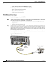
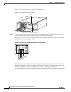
Chapter 2 Installing a PIX Firewall
Installing a PIX 520 or Earlier Model
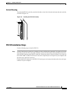
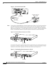
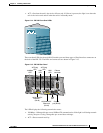
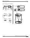
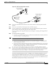
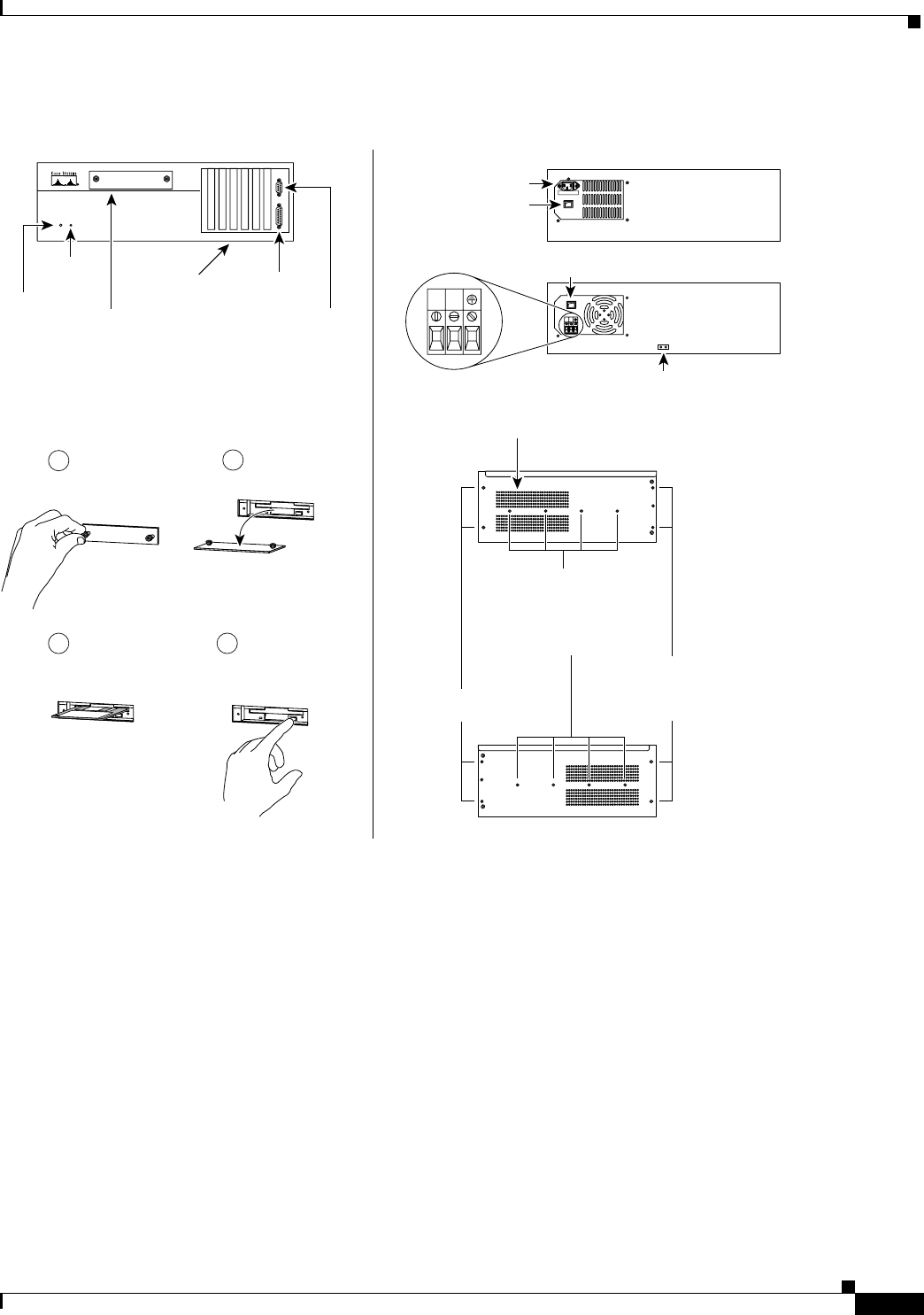
Figure 2-17 PIX 520 Front, Rear, and Side Panels.
PIX Firewall
SERIES
RE
S
E
T
Au
to-Ra
nge Selec
tion
L:90
-1
35
V H:180-270V
Power connector
DC power connector
Slots for
network
interfaces
Front Rear
Power switch
Power switch
Ground lugs
Diskette
compartment
Right side
Left side
Fan duct
Holes to connect
rackmount slide rails
(must be purchased
separately from
outside vendor)
AC
DC
Failover
connector
Console
connector
Insert PIX
security appliance
diskette
Reset
button
Power
light
1
2
4
3
To access,
loosen screws
counterclockwise
Set plate
on surface
To remove
diskette,
push button
10656
+
–
+–
Rackmount
holes
Holes to connect
rackmount brackets
(if rackmounting
is desired)