2-21
Installation Guide for the Cisco Secure PIX Firewall Version 5.2
78-11180-01
Chapter 2 Installing a PIX Firewall
Installing a PIX 520 or Earlier Model
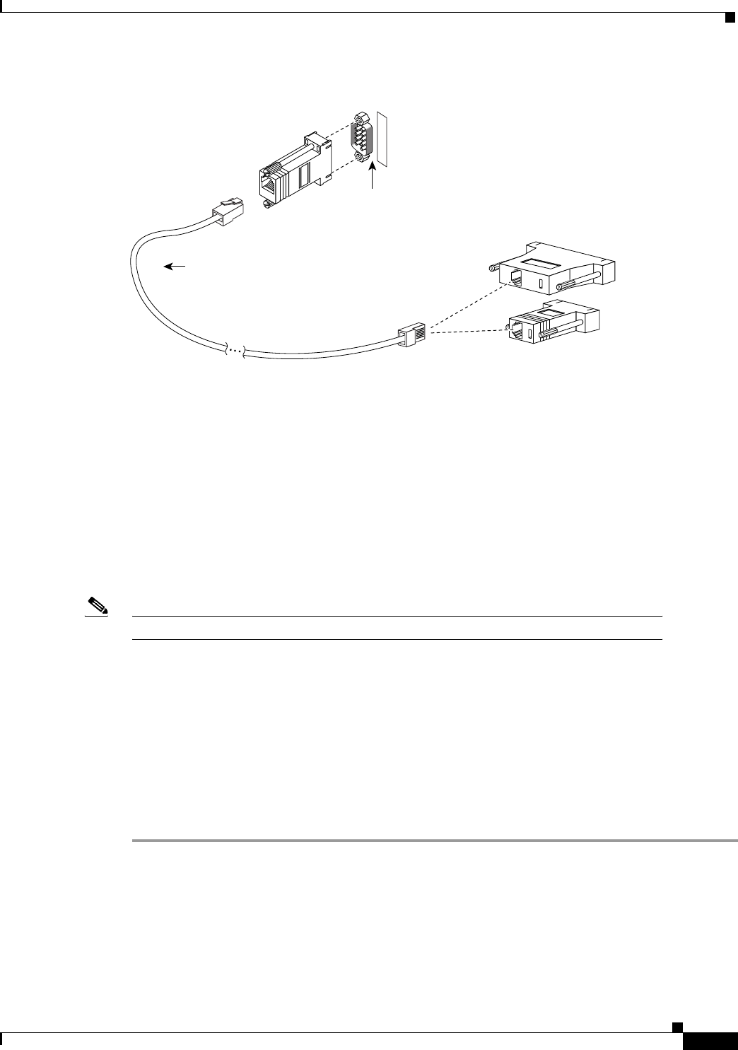
Figure 2-23 PIX Firewall Serial Cable Assembly
Step 3
Connect one of the DB-9 serial connectors to the console connector on the front panel of the PIX
Firewall.
Step 4 Connect one end of the RJ-45 null modem cable to the DB-9 connector.
Step 5 If you are installing an AC voltage PIX Firewall, connect the PIX Firewall unit’s power cord to the
power connector on the rear panel of the unit, and to a power outlet.
If you are installing a DC voltage PIX Firewall, refer to Chapter 8, “Installing a DC Voltage PIX 515
or PIX 520.”
Step 6 The following options are available:
a. If you have a second PIX Firewall to use as a failover unit, install the failover feature and cable as
described in Chapter 3, “Installing Failover.”
Note Do not power on the failover units until the primary unit has been configured.
b. If needed, install the PIX Firewall Syslog Server as described in Chapter 4, “Installing the PIX
Firewall Syslog Server (PFSS).”
c. If you need to install an optional circuit board such as a single-port Ethernet board, or the four-port
Ethernet board, refer to Chapter 5, “Opening a PIX Firewall Chassis,” for information about how
to open the top panel of the chassis to install circuit boards.
d. If you need to install additional memory, refer to Chapter 6, “Installing a Memory Upgrade.”
Step 7 If you are ready to start configuring the PIX Firewall, power on the unit. When the unit is powered on,
refer to the Cisco PIX Firewall Configuration Guide, Version 5.2. Alternatively, you can use the PIX
Firewall Setup Wizard described in Chapter 9, “Installing the PIX Firewall Setup Wizard.”
If you need to download software version 5.1 or higher, use the “Boothelper Installation” section. If
your site downloads configuration images from a TFTP server, use the section “Downloading a
Software Image over TFTP” to learn how you can access boot mode while the PIX Firewall is starting
up. The PIX Firewall pauses for 10 seconds for you to press the Escape key or send a BREAK character.
On a Windows system, press the Esc key to access boot mode.
DB-9-to-DB-25
serial cable
(null-modem)
Computer serial port
DB-25 or DB-9
Console
port (DB-9)
PIX security appliance
console connector
C
O
N
S
O
L
E
12275


