


2-13
Installation Guide for the Cisco Secure PIX Firewall Version 5.2
78-11180-01
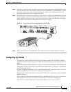
Chapter 2 Installing a PIX Firewall
Installing a PIX 525
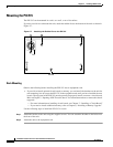
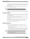
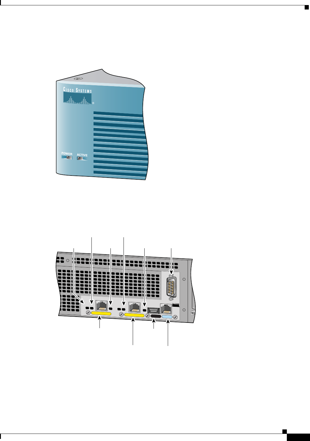
• ACT—On when the unit is the Active failover unit. If failover is present, the light is on when the
unit is the Active unit and off when the unit is in Standby mode.
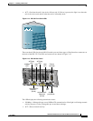
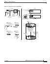
Figure 2-14 PIX 525 Front Panel LEDs
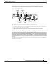
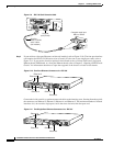
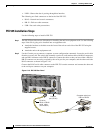
There are three LEDs for the each RJ-45 interface port and three types of fixed interface connectors on
the back of the PIX 525. The LEDs and connectors are shown in Figure 2-15.
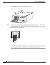
Figure 2-15 PIX 525 Rear Panel
The LEDs display the following transmission states:
• 100 Mbps—100 megabits per second 100BaseTX communication. If the light is off during network
activity, that port is using 10 megabits per second data exchange.
• ACT—Shows network activity.
44568
F
A
I
L
O
V
E
R
100M
bps A
C
T
100M
bps A
C
T
LIN
K
LIN
K
P
IX
-525
10/100 ETHERNET 1
10/100 ETHERNET 0
USB
CONSOLE
44567
10/100 BaseTX
Ethernet 0
(RJ-45)
10/100 BaseTX
Ethernet 1
(RJ-45)
Console
port (RJ-45)
USB
port
Failover
connector
LINK
LED
LINK
LED
100Mbps
LED
ACT(ivity)
LED
ACT(ivity)
LED