


56
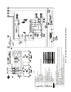
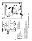
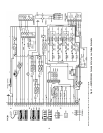
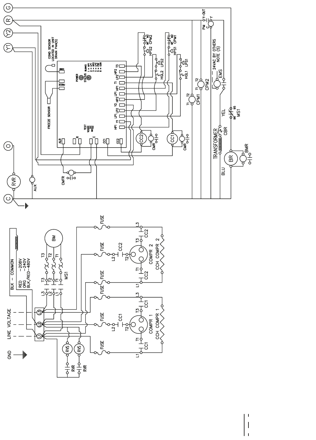
Fig. 39 — 50BVT,U,V034 Constant Volume Wiring Schematic
A50-8251
LEGEND
NOTES:
1. See unit nameplate for electrical rating.
2. All field wiring must be in accordance with NEC-NFPA #70.
3. 208/230-v units are factory wired for 230-v operation. For 208-v operation, remove ORG lead and replace
with RED lead. Cap all unused leads.
4. Check phase rotation on all scroll compressor units. Reverse rotation will damage the compressor and void
unit warranty.
5. For alternative EMS coil voltages, consult factory.
6. UPM board includes built in 30 to 60-second random start, 5-minute delay on break, 90-second low pres-
sure bypass, and 5-second second stage delay.
7. Setting the test mode jumper to yes reduces all time delays to 5 seconds.
Standard Components Legend: Optional Components Legend:
#1 — First Stage CMFR — Compressor Malfunction Relay
#2 — Second Stage CMR — Compressor Monitor Relay
BM — Blower Motor EMS — Energy Management System Relay
BR — Blower Relay FSR — Freeze/Condensate Sensor Relay
CBR — 24-vac Circuit Breaker Freeze/Condensate Sensor Module (includes FSR)
CC — Compressor Contactor Condensate Sensor
CCH — Crankcase Heater (When Supplied) Freeze Sensor
CPM — Compressor Protection Module
HPS — High Pressure Switch
LPS — Low Pressure Switch
MS — Motor Starter
RVR — Reversing Valve Relay (Heat Pumps Only)
RVS — Reversing Valve Solenoid (Heat Pumps Only)
Factory Wire
Field Wire