


51
Evaporator Fan Performance Adjustment —
To change fan speeds from factory settings:
1. Shut off unit power supply.
2. Loosen nuts on the 4 carriage bolts in the mounting
base. Using adjusting bolts and plate, slide the motor
and remove the belt.
3. Loosen movable-pulley flange setscrew.
4. Screw the movable flange toward the fixed flange to
increase speed, and away from the fixed flange to
decrease speed. Increasing the fan speed increases the
load on the motor. Do not exceed the maximum speed
specified in Tables 3A and 3B.
5. Set the movable flange at nearest keyway of the pulley
hub and tighten the setscrew. (See Tables 3A and 3B
for speed change for each full turn of pulley flange.)
6. Replace and tighten the belts (see Belt Tension Adjust-
ment section).
7. Restore power to the unit.
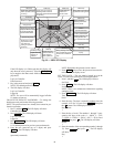
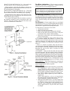
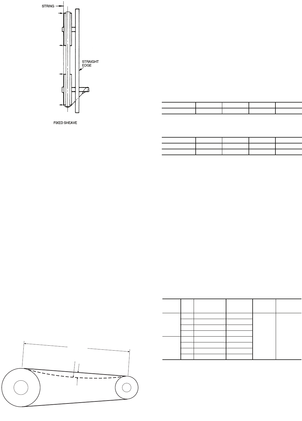
To align fan and motor pulleys:
1. Loosen fan pulley setscrews.
2. Slide fan pulley along fan shaft.
3. Make angular alignment by loosening motor from
mounting plate.
4. Restore power to unit.
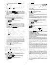
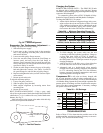
BELT TENSION ADJUSTMENT — Using a gage, apply
4 lb of force to the center of the belt and adjust the tension until
a deflection of
1
/
64
-in. is achieved for every inch of shaft center
distance. See Fig. 37.
Ideal belt tension is the lowest value under which belt slip
will not occur at peak load conditions.
Charging the System
REMOTE AIR-COOLED UNITS — The 50BVE,K,U,X units
are shipped with a holding charge of dry nitrogen. Remote
condensers, interconnecting piping, and refrigerant to charge the
system are all field supplied.
To evacuate the system, refer to GTAC II, Module 4, Dehy-
dration for Proper Evacuation and Dehydration Techniques.
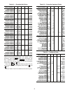
To charge the 50BVE,K,U,X systems:
1. Add an initial minimum refrigerant charge after evacu-
ation to allow the unit to start. Refer to Tables 25A and
25B. Additional refrigerant will be added based on the
length of interconnecting piping and vertical separa-
tion between the indoor unit and the condenser(s).
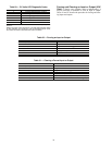
Table 25A — Minimum Operating Charge (lb),
50BVE,K Units Matched with 09DK Condensers
Table 25B — Minimum Operating Charge (lb),
50BVU,X Units Matched with 09DK Condensers
2. To finish charging the system, make sure the unit
is running at full-load operating conditions. Charge to
a clear sight glass. Refer to GTAC II, Module 5,
Charging, Recovery, Recycling and Reclamation and
the Refrigerant Service Techniques manual for proper
charging techniques.
3. Add 10 lb of R-22 or R-410A over a clear sight glass
to flood subcooler section of the condenser coils.
4. Alternately, and as a double-check, when properly
charged at full-load operating conditions, there should
be 15 F subcooling entering the TXV (the difference
between saturated condenser temperature and actual
liquid temperature entering the TXV).
Compressor Oil — All units are factory charged with
oil. It is not necessary to add oil unless compressor(s) is re-
moved from the unit. If necessary, oil can be removed/charged
via Schrader fitting. Operate the system at high evaporator tem-
perature prior to oil recharge to assist oil return to the compres-
sor(s) from other system components. If necessary, recharge
the system as shown in Table 26.
Table 26 — Oil Recharge
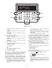
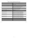
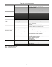
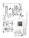
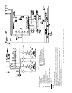
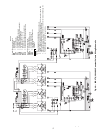
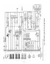
TROUBLESHOOTING
Refer to Tables 27-29 to determine the possible cause of the
problem and the associated procedure necessary to correct it.
See Fig. 38-47 for unit and control wiring.
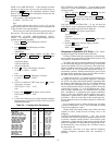
UNIT SIZE 020 024 028 034
Circuit 1...2 8.1...8.1 9.1...9.1 9.1...9.1 18...18
UNIT SIZE 034 044 054 064
Circuit 1...2 18...18 10...10 18...18 18...18
Circuit 3...4 - 10...10 18...18 18...18
50BV
UNIT
SIZE COMPRESSOR
OIL
RECHARGE
(oz)
OIL
TYPE
PART
NUMBER
C,E,
Q,J,K
020 ZR94KC 81
3GS 150
viscosity
yellow
mineral
oil
P903-0101
024 ZR108KC 106
028 ZR144KC 106
034 ZR19M3 137
T,U,
V,W,X
034 ZR19M3 137
044 ZR125KC 106
054 ZR16M3 137
064 ZR19M3 137
BELT SPAN
LB FORCE
DEFLECTION
Fig. 37 — Fan Belt Tension
a50-7136ef
Fig. 36 — Sheave Alignment
a50-7135tf