


42
VAV Unit Start-Up
PERFORM AUTOMATIC RUN TEST — The 50BVJ,K,
W,X unit controls are programmed with an automatic run test
that checks connection and operation of major components. To
perform the run test:
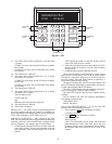
Verify that the control display (LID [Local Interface Dis-
play] device/system monitor) interface cable is connected to in-
ternal jack on main controller; that the fire alarm/shutdown
switch input (FSD) has a factory jumper or field input; and that
the Local/Off/Remote switch is set to the REMOTE position
(Fig. 17).
NOTE: When the Local/Off/Remote switch is in the
REMOTE position, the controller time schedule is pre-set
(from the factory) as unoccupied. This means that the unit will
not turn on until the run test is enabled. However, if the con-
troller schedule has already been modified in the field, and the
current time of day is occupied, then the supply fan will start.
The run test will shut the fan down when it begins. The run test
will complete and then the supply fan will automatically
restart.
NOTE: If the Local/Off/Remote switch is in the OFF position,
it is normal for the red alarm light on the display panel to be lit,
indicating that the unit is disabled.
NOTE: If the light stays on when the switch is moved to
REMOTE, or if any other problems occur during the run test,
refer to the Troubleshooting section of this manual.
To perform the run test:
1. Turn unit power on.
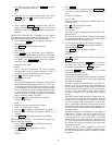
The LID display will show the controller identification,
time, and date (Fig. 32):
OMNIZONE VPAC
hh:mm mm-dd-yy
2. Press 3 and then . The LID display will show:
Controller Password
3. Press . The LID display will show:
Log in to Controller
Enter Password
NOTE: The LID display has two modes: Edit mode and
Status/Maintenance mode. If the LID display is in Edit
mode, then the display will only show the word “pass-
word.” Press the key to toggle to the Status
mode.
Press the to display:
Log in to Controller
Enter Password
4. Key in the password and press .
NOTE: The default password is 1111.
5. The LID display will show:
Log in to Controller
Logged In
6. Press 37 . The display will show:
Custom Program
7. Press . The display will show:
2.0 Global Dictionary
OMNIZONE
8. Press (NOTE: Display will flash and is
now in edit mode.) The display will show:
2.0 Global Dictionary
OMNIZONE
9. Press . The display will show:
Compressor Stages
2.00 (sizes 020-034)
4.00 (sizes 044-064)
10. If the number of compressor stages displayed is incorrect,
then enter the correct number. Input 2.00 for sizes 020-
034 or 4.00 for sizes 044-064, then Press . The
display will show:
Compressor Stages
2.00 (sizes 020-034)
4.00 (sizes 044-064)
11. Press . The LID display will show:
Hardware Points
12. Press again. The LID display will show:
Software Points
13. Press . The LID display will show:
Compressor 1 Status
14. Press 6 times. The LID display will show:
Factory/Field Test
Stop
15. Press 1 then , The LID display will show:
Factory/Field Test
Start
NOTE: At this point, the yellow warning light on the display
panel will be lit and will stay on throughout the run test. After
each successful step, the red alarm light will blink once.
16. The control module will now check if there is input from
DHS, FSD, SAT, DSP, and CSMUX.
If the control does not receive open/closed/in range/in
range/in range, the red alarm LED will go on and the test
will stop.
If the inputs are okay, the red alarm LED blinks once and
the test continues.
17. Next, the control forces the supply fan (SF) and all of the
compressors (COMP) off, and waits 15 seconds.
18. The control forces SF on and SPEED to 20 percent and
then waits 30 seconds.
If the VFD display shows: 12.0 Hz, the remote and auto
LEDs blink, and the fan goes on, then the red LED on the
control module blinks once and the test continues.
19. The control forces SF on and SPEED to 35 percent and
then waits 30 seconds.
If the VFD display shows: 21.0 Hz, the remote and auto
LEDs blink, and the fan goes on, then the red LED on the
control module blinks once and the test continues.
20. The control forces SF off then waits 15 seconds.
If the VFD display shows: Off, the remote and auto LEDs
are off, and the fan goes off, then the red LED on the con-
trol module blinks once and the test continues.
NOTE: The steps below will be completed for the number of
compressors configured.
21. The control forces CMP1 (compressor 1) on then waits
5 seconds.
If CSMUX is not in range, the red LED will go on and the
test will stop.
If CSMUX is in range, the red LED blinks once and the
test continues.
22. The control forces CMP1 off.
SET
ENTER
EXPN/EDIT
EXPN/EDIT
ENTER
ALGO
ENTER
EXPN/EDIT
ENTER
ENTER
STAT
STAT
ENTER
ENTER