


23
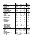
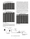
Table 6A — Hot Water Pressure Drop
50BVC,E,J,K,Q Units
LEGEND
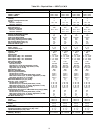
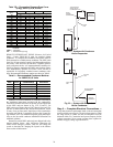
Table 6B — Hot Water Pressure Drop
50BVT,U,V,W,X Units
LEGEND
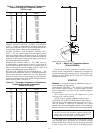
Pipe sizes should be selected based on the head pressure
available from the pump. Water velocity should not exceed
8 fps. Design the piping system for approximately 3 ft of loss
per 100 equivalent ft of pipe. The piping system should allow
for expansion and minimize vibration between the unit and
piping system.
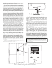
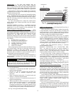
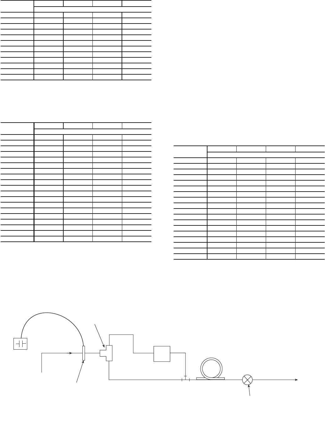
WATER ECONOMIZER (Optional) — The optional waterside
economizer (pre-cooling coil) is factory-installed and piped inter-
nally, in series with the condenser water circuit (Fig. 21). A divert-
ing valve and factory controls are included with the option. Only
one set of field connections needs to be made for condenser water
and economizer water. In addition, when the unit is shipped with
the economizer option, the economizer drain must be connected
to a separate trap. Follow the same steps for the economizer drain
as described for the evaporator condensate drain. An Aquastat is
used to modulate water flow through the economizer. The control-
ler is mounted to the low voltage control box. Electrical connec-
tions are factory installed and wired. The remote bulb is shipped
internal to the unit and requires field mounting. Care should be
taken not to dent the bulb or miscalibration may occur. The
Aquastat has a temperature range adjustment (–30 F to 100 F) and
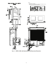
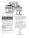
is field set. See Fig. 2-14 for connection locations and sizes. See
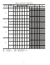
Tables 7A and 7B for economizer waterside pressure drop data.
The waterside economizer can also be ordered without
factory-installed piping or controls. This offers additional
flexibility for specific applications. In this case, the coil is
factory mounted, but all supply and return piping and controls
are field supplied.
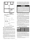
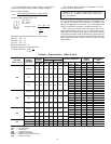
Table 7A — Economizer Pressure Drop Curve
(ft wg), 50BVC,E,J,K,Q Units
LEGEND
FLOW RATE
(gpm)
SIZE 020 SIZE 024 SIZE 028 SIZE 034
Pressure Drop (ft wg)
10 0.7 0.7 0.7 —
15 1.5 1.5 1.5 —
20 2.6 2.6 2.6 —
25 4.0 4.0 4.0 —
30 5.8 5.8 5.8 0.1
35 7.8 7.8 7.8 0.1
40 10.2 10.2 10.2 0.1
45 12.9 12.9 12.9 0.2
50 15.8 15.8 15.8 0.2
55 ———0.3
60 ———0.3
65 ———0.4
GPM — Flow Rate
PD — Pressure Drop (ft wg)
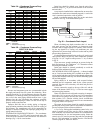
FLOW RATE
(gpm)
SIZE 034 SIZE 044 SIZE 054 SIZE 064
Pressure Drop (ft wg)
45 2.4 — — —
50 3.0 — — —
55 3.6 — — —
60 4.3 — — —
65 5.0 — — —
70 5.7 — — —
75 6.6 — — —
80 7.4 — — —
85 8.4 — — —
90 9.3 2.5 2.5 2.5
100 — 3.1 3.1 3.1
110 — 3.7 3.7 3.7
120 — 4.4 4.4 4.4
130 — 5.1 5.1 5.1
140 — 5.9 5.9 5.9
150 — 6.7 6.7 6.7
160 — 7.6 7.6 7.6
170 — 8.6 8.6 8.6
180 — 9.6 9.6 9.6
GPM — Flow Rate
PD — Pressure Drop (ft wg)
FLOW RATE
(gpm)
SIZE 020 SIZE 024 SIZE 028 SIZE 034
Pressure Drop (ft wg)
35 8.9 — — —
40 11.5 11.0 — —
45 14.4 13.8 — —
50 17.6 16.9 16.9 —
55 21.1 20.4 20.4 —
60 24.9 24.1 24.1 3.5
65 29.0 28.1 28.2 4.1
70 34.4 32.5 32.5 4.7
75 — 37.1 37.2 5.4
80 — 42.1 42.1 6.1
85 — — 47.4 6.9
90 — — 52.9 7.7
95 — — 58.7 8.5
100 — — 64.9 9.4
105 — — — 10.3
110 — — — 11.3
115 — — — 12.3
120 — — — 13.4
GPM — Flow Rate
PD — Pressure Drop (ft wg)
motor
FLUID IN
N.O.
AQUASTAT
MBV
“BULB STRAPPED
TO FLUID” IN LINE
(FIELD INSTALLED)
N.O.
N.C.
3-WAY MOTORIZED
BALL VALVE
WATERSIDE
ECONOMIZER
COIL
FLUID TO REFRIGERANT
HEAT EXCHANGER
POSITIVE SHUT-OFF SOLENOID
VALVE FOR VARIABLE SPEED
PUMPING SYSTEM
(FIELD INSTALLED)
Fig. 21 — Optional Water Economizer
a50-7269ef