


52
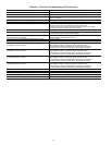
Table 27 — Run Test Troubleshooting (VAV Units Only)
NOTE: For more information on VAV controls, refer to the 50BV,XJ Controls Operation and Troubleshooting Manual.
PROBLEM POSSIBLE CAUSE
Control modules do not have lights when unit power is on. Transformer open. Circuit breaker open. Power wiring open. Module failure.
Control display does not light up when unit power is on. Connection location. Interface cable open. Display failure.
Run test will not start. Pre-existing ALARM (red)? Not “Logged in” with password.
Switch not in local.
WARN (yellow) LED does not light during run test. Wiring open. Lamp failure. Control module failure.
ALARM (red) LED does not light during run test. Wiring open. Lamp open. Control module failure.
Run test stops, ALARM (red) LED light is lit after it blinks once. Bypass switch to LINE. Mode switch to OFF. Duct high
pressure switch open. Fire shutdown input or jumper open.
Supply air temp out of range. Duct static pressure sensor out of range.
Compressor resistor board wiring error or failure.
Fan does not start/ALARM (red) LED blinks 2 times. Fan relay failure.
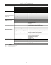
Run test stop, ALARM (red) LED is lit after blinking 3 times. Wiring open. VFD connection error. VFD setup error. Fan relay failure.
Current isolator failure. Control module failure.
Run test stop, ALARM (red) LED is lit after it blinks 4 times.
Fan does not increase speed.
VFD connection error. VFD setup error.
Current isolator load adjustment too low.
Fan does not stop after ALARM (red) LED blinks 5 times. Fan relay failure.
Fan rotation is backwards. VFD to motor wiring sequence error. VFD setup error.
Run test stop, ALARM (red) LED is lit after blinking 6 times.
Compressor 1 does not start.
Wiring open. Compressor resistor board wiring error or failure.
High pressure switch, low pressure switch, coil frost switch,
or compressor protection module open. Compressor relay failure.
Contactor failure. Control module failure. No refrigerant charge.
Run test stop, ALARM (red) LED is lit after blinking 7 times.
Compressor 2 does not start.
Wiring open. Compressor resistor board wiring error or failure.
High pressure switch, low pressure switch, coil frost switch,
or compressor protection module open. Compressor relay failure.
Contactor failure. Control module failure. No refrigerant charge.
Run test stop, ALARM (red) LED is lit after blinking 8 times.
Compressor 3 does not start.
Wiring open. Compressor resistor board wiring error or failure.
High pressure switch, low pressure switch, coil frost switch,
or compressor protection module open. Compressor relay failure.
Contactor failure. Control module failure. No refrigerant charge.
Run test stop, ALARM (red) LED is lit after blinking 9 times.
Compressor 4 does not start.
Wiring open. Compressor resistor board wiring error or failure.
High pressure switch, low pressure switch, coil frost switch,
or compressor protection module open. Compressor relay failure.
Contactor failure. Control module failure. No refrigerant charge.
Compressor rotation is backwards. Field power wiring sequence error. Compressor power wiring sequence error.
“C” message in I/O status display. No input signal or communication failure.
“Service” message in I/O status display. Value is forced from 6400 keypad entry.
“Supervisor” message in I/O status display. Value is forced from network communication (i.e., PC).
ALARM (red) LED always on, will not enter run test. SAT, DSP, CSMUX, DHS, or PHASE input values. Mode switch OFF.