


24
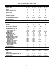
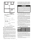
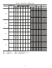
Table 7B — Economizer Pressure Drop Curve
(ft wg), 50BVT,U,V,W,X Units
LEGEND
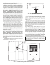
REMOTE REFRIGERANT PIPING (Remote Air-Cooled
Only) — Carrier 50BVE,K,U,X units are supplied without
condensers. To complete the installation, these units must be
field connected to a suitable remote condenser. The 50BV units
from 18 to 30 tons contain 2 equally sized independent refriger-
ant circuits. Units from 40 to 60 tons have 4 separate equal ca-
pacity refrigerant circuits. It is important that the condenser cir-
cuiting be properly matched to the 50BV unit circuiting. Other-
wise, unsatisfactory operation will result. Carrier will not be
responsible for improperly matched remote condenser selec-
tions. Recommended condenser matches are shown in Table 8.
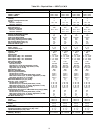
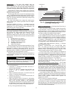
Table 8 — Recommended Condenser Matches
for 50BVE,K,U,X Units
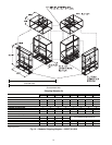
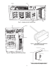
Install the air-cooled condenser or condensers according to
the installation instructions provided with the condenser(s).
Connection locations and sizes for the hot gas and liquid lines
on the 50BV units are shown in Fig. 2-14, 22 and 23. For
50BV units up to 30 tons, there will be 2 hot gas lines and 2 liq-
uid lines to install between the unit and the condenser. Above
30 tons, 4 hot gas lines and 4 liquid lines will be installed be-
tween the unit and the 2 condensers. Refer to the System De-
sign Manual, Part 3 for standard refrigerant piping techniques.
Also see the air-cooled condenser installation instructions for
additional guidance.
Remote air-cooled 50BV units (only) are shipped with a dry
nitrogen holding charge. After refrigerant connections are
made, release nitrogen, evacuate, leak test, and charge the
system as described in Charging the System in the Mainte-
nance section of this manual.
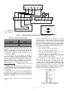
Step 5 — Complete Electrical Connections —
Verify that electrical requirements listed on the unit nameplate
match available power supply. The unit voltage must be within
the range shown in Tables 9A and 9B and phases must be
balanced within 2%. Contact the local power company for line
voltage corrections. Never operate a motor where a phase im-
balance in supply voltage is greater than 2%.
FLOW RATE
(gpm)
SIZE 034 SIZE 044 SIZE 054 SIZE 064
Pressure Drop (ft wg)
60 13.1 — — —
70 17.9 — — —
80 23.5 5.8 — —
90 29.8 7.3 — —
100 36.9 9.1 9.0 —
110 44.8 11.0 11.0 —
120 53.4 13.1 13.1 13.1
130 — 15.4 15.4 15.4
140 — 17.9 17.9 17.9
150 — 20.6 20.6 20.6
160 — 23.5 23.5 23.5
170 — — 26.6 26.5
180 — — 29.8 29.8
190 — — 33.3 33.2
200 — — 36.9 36.8
210 ———40.7
220 ———44.7
230 ———48.9
240 ———53.3
GPM — Flow Rate
PD — Pressure Drop (ft wg)
50BV
NO. OF
CKTS
CONDENSER(S)
CONDENSER
CIRCUITING
020 2 09DK020 (1) 50/50%
024 2 09DK024 (1) 50/50%
028 2 09DK028 (1) 50/50%
034 2 09DK034 (1) 50/50%
044 4 09DK024 (2) 50/50% (each)
054 4 09DK028 (2) 50/50% (each)
064 4 09DK034 (2) 50/50% (each)
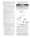
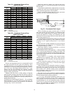
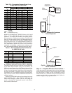
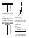
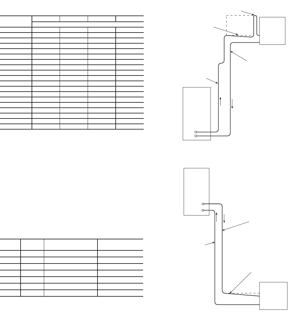
LIQUID
LINE
SLOPE
TOWARD
CONDENSER
TRAP (MUST BE
ABOVE TOP OF
CONDENSER COIL)
REMOTE
CONDENSER
HOT GAS
LINE
50BV
UNIT
Fig. 22 — System with Condenser
Above Evaporator
a50-7270ef
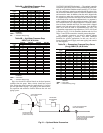
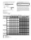
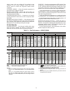
50BV
UNIT
REMOTE
CONDENSER
HOT GAS
LINE
LIQUID
LINE
SLOPE TOWARD
CONDENSER
a50-7271ef
Fig. 23 — System with Evaporator
Above Condenser