


19
ACOUSTICAL CONSIDERATIONS — Proper acoustical
considerations are a critical part of every system’s design and
operation. Each system design and installation should be
reviewed for its own unique requirements. For job specific
requirements, contact an acoustical consultant for guidance and
recommendations.
In general, to reduce noise, consider the following:
• Locate mechanical room and ducts away from noise
sensitive locations. Whenever possible, work with the
architect to locate the equipment rooms around the
perimeters of restrooms, hallways, fire escapes, stair
wells, etc., to reduce noise transmission. This allows not
only for isolation from radiated sound but also enables
the contractor to route duct systems around sensitive
locations.
• Construct the equipment room of concrete block or use a
double offset stud wall with interwoven insulation. Seal
all penetrations.
• Design the system for low total static pressure.
• Use suitable vibration isolation pads or isolation springs
according to the design engineer's specifications.
• A flexible canvas duct connector is recommended on
both the supply and return air sides of units to be
connected to system ductwork.
• Use a minimum of 15 ft of return ductwork between the
last air terminal or diffuser and the unit.
• Insulate supply and return ducts with 2-in., 3-lb density
insulation.
• Round duct is recommended. If rectangular ductwork is
used, keep aspect ratios as small as possible (i.e., as close
to square as possible).
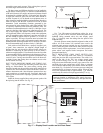
• Avoid any direct line of sight from return air grilles
into the unit's return. If return air is to be ducted to an
equipment room, an elbow should be installed within the
equipment room.
• Running a return air drop to near the floor of the room
will aid in sound attenuation.
• Do not exceed the recommended supply duct velocity of
2,000 fpm.
• Do not exceed the recommended return duct velocity of
1,000 fpm.
• Use turning vanes on 90-degree elbows.
• Place isolation springs under each corner and under each
compressor if utilized.
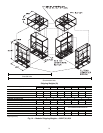
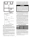
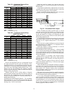
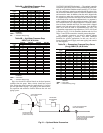
ASSEMBLING MODULAR UNITS — 50BVT,U,V,W,X
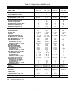
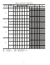
30 to 60 ton units ship in the number of pieces shown in Table
2. Reassemble the unit. Use the loose hardware provided in the
main air-conditioning section and the instructions below.
1. The filter/economizer section ships bolted to the main air-
conditioning section and can be removed in the field.
When reattaching the filter/economizer section to the
main air-conditioning section, place the filter side of the
filter/economizer section facing out and away from the
main air conditioning section.
2. If the unit has 2 filter/economizer and 2 main air-
conditioning sections (40 through 60 ton units), bolt the
remaining filter/economizer section and main air-
conditioning section together, as in Step 1.
3. For units with 2 filter/economizer and 2 main air-
conditioning sections, use the provided unions to assem-
ble the water connections between the 2 additional
sections joined in Step 2.
4. For units with multiple air conditioning sections, connect
the condensate drain hoses from the “B” side of the unit
to the drain manifold on the “A” side of the unit.
5. For unit sizes 044-064, connect power wiring from the
main terminal block in the “A” side of the unit to the
power terminal block in the “B” side of the unit.
6. For VAV units only, connect the plenum tubing, coiled
behind the VAV control panel, to the bulkhead fittings
located in the discharge of the supply fan. This connects
the high pressure supply to the high side of the duct high
static pressure switch.
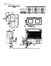
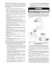
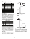
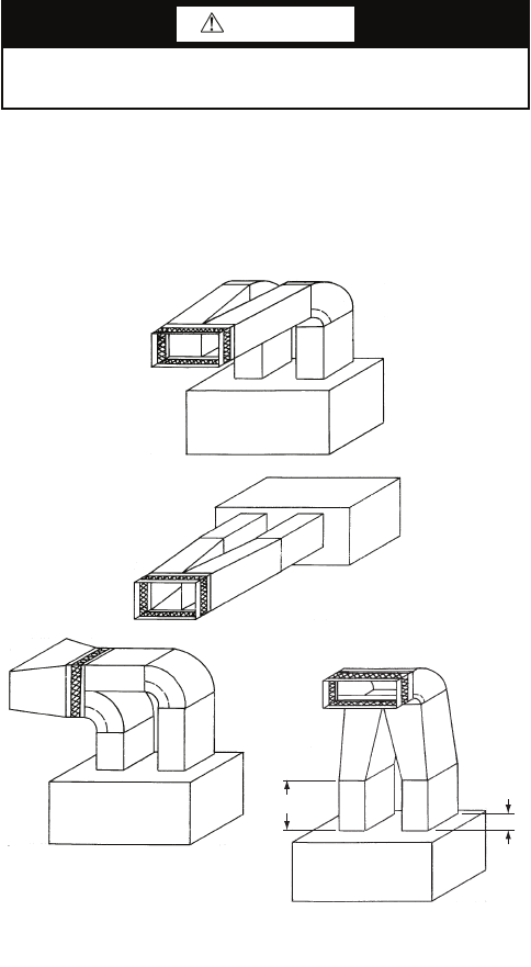
Step 3 — Install Ductwork — The VAV units must
use a “pair of pants” configuration as shown in Fig. 15. Refer
to the Carrier System Design Manual or ASHRAE (American
Society of Heating, Refrigerating and Air Conditioning Engi-
neers) standards for the recommended duct connection to unit
with 2 fans.
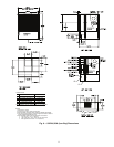
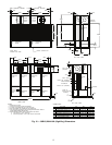
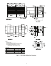
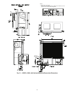
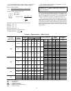
A supply air outlet collar and return air duct flange are pro-
vided on all units to facilitate duct connections. Refer to dimen-
sional drawings (Fig. 2-14) for connection sizes and locations.
A flexible canvas duct connector is recommended on both
supply and return air sides of the units to be connected to the
system ductwork.
All metal ductwork should be adequately insulated to avoid
heat loss or gain and to prevent condensation from forming on
the duct walls. Uninsulated ductwork is not recommended, as
the unit's performance will be adversely affected.
Do not connect discharge ducts directly to the blower
outlet(s). The factory filter should be left in place on a free
return system.
If the unit will be installed in a new installation, the duct
system should be designed in accordance with the System De-
sign Manual, Part 2 and with ASHRAE (American Society of
Heating, Refrigeration and Air Conditioning Engineers) proce-
dures for duct sizing. If the unit will be connected to an existing
duct system, check that the existing duct system has the capaci-
ty to handle the required airflow for the unit application at an
CAUTION
Remove all shipping blocks, if any, under blower housing
or damage to the fan may occur.
Fig. 15 — Typical Fan Discharge Connections for
Multiple Fan Units
NOTE: A = 1
1
/
2
to 2
1
/
2
B
A
B
a50-8357.eps