


20
acceptable system static pressure. If the existing duct system is
too small, larger ductwork must be installed.
The duct system and diffusers should be sized to handle the
design airflow volumes quietly. To maximize sound attenuation
of the unit's blower(s), the supply and return air plenums should
be insulated for a length of at least 15 ft from the unit. Direct line
of sight from return air grilles into the unit's return should be
avoided. If return air is to be ducted to an equipment room, an
elbow should be installed within the equipment room. Running a
return air drop to near the floor of the room will aid in sound
attenuation. Avoid transmitting vibrations generated by the
movement of air in the ducting to the walls of the building. This
is especially important where ductwork penetrates walls. The
maximum recommended return air velocity is 1,000 fpm. Lower
return air velocities will result in lower sound power levels. The
use of round supply duct plenums should be considered, as it
will significantly reduce low frequency sound at the equipment
room. If rectangular supply plenums are used, the aspect ratio of
the duct should be kept as small as possible (i.e., as close to
square as possible). The large, flat surface areas associated with
large aspect ratio duct systems will transmit sound to the space,
and the potential for duct-generated noise is increased. The max-
imum recommended supply air duct velocity is 2,000 fpm.
Units with two fans should have a properly designed “pair
of pants” duct connection. An adequate straight length of
ducting from the unit should be allowed before elbows are
installed. If connecting an elbow directly to the fan outlet, a
minimum straight length of 2 fan diameters from the fan outlet
is recommended. Elbows should turn in the direction of fan ro-
tation, if possible. Abrupt turns will generate air turbulence and
excessive noise. Turning vanes should be used in all short radi-
us bends. Ensure that ducting does not obstruct access to the
unit for routine servicing.
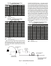
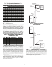
DUCT STATIC PRESSURE PROBE AND TUBING (VAV
Only) — On VAV systems, the duct static pressure sensor and
tubing are field-mounted. The sensor tubing sensing point
should be located near the end of the main supply trunk duct in
a position free from turbulence effects and at least 10 duct di-
ameters downstream and 4 duct diameters upstream from any
major transitions or branch take-offs. Incorrectly placing the
sensing point could result in improper operation of the entire
VAV sys te m.
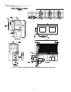
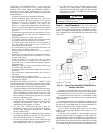
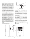
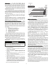
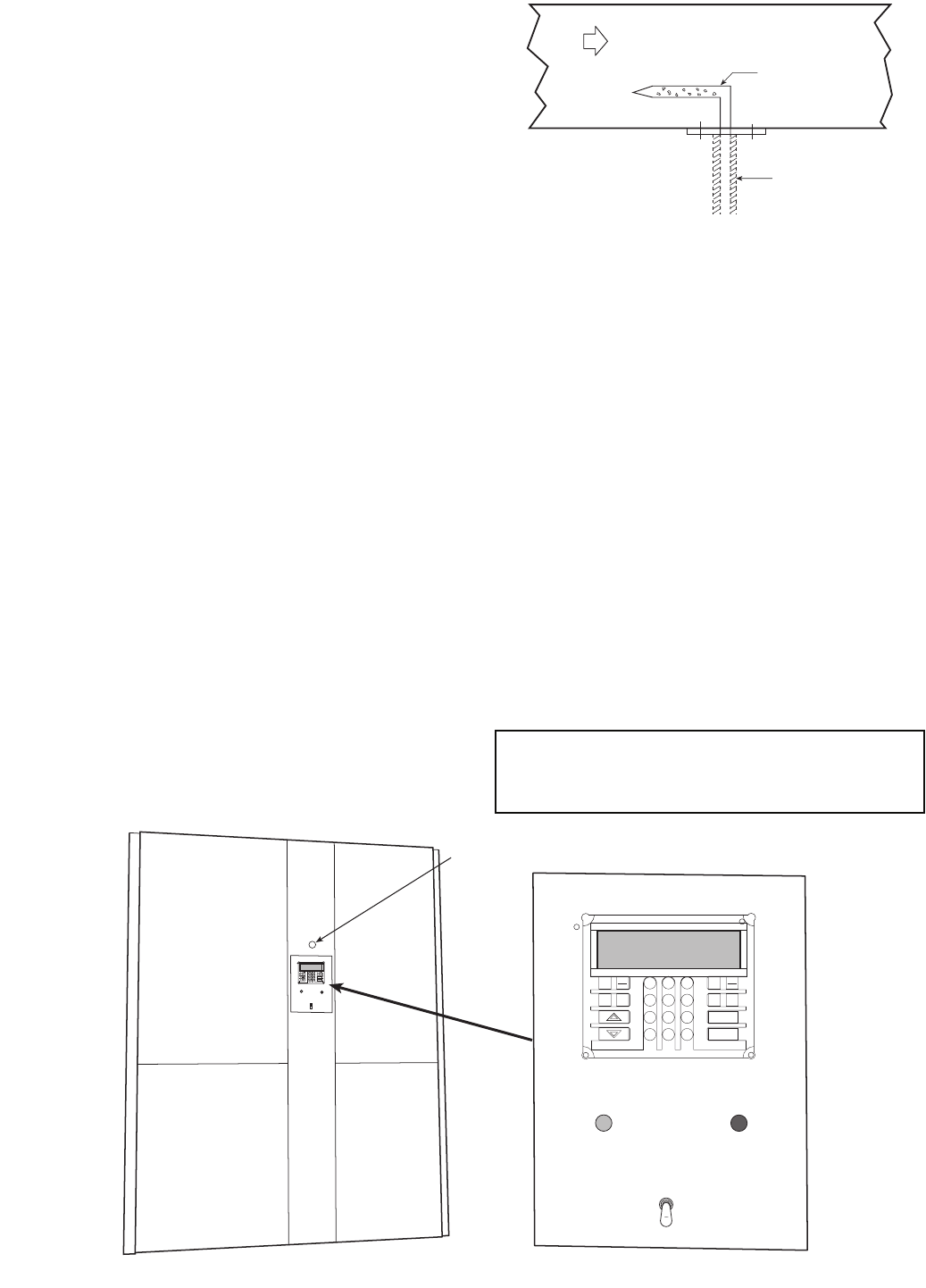
Install the factory-supplied duct static pressure probe with
the tip facing into the airflow. See Fig. 16.
Use
1
/
4
-in. OD approved polyethylene tubing for up to
50 ft (
3
/
8
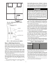
-in. OD for 50 to 100 ft) to connect the probe to the
bulkhead fitting mounted above the unit display panel
(Fig. 17). Carefully route the tubing from the probe to this
bulkhead fitting.
The static pressure control should be adjusted so that, at full
airflow, all of the remote VAV terminal boxes receive the
minimum static pressure required plus any downstream resis-
tance. Control the system to the lowest static pressure set point
that will satisfy airflow requirements. Lower static pressure set
points reduce total required brake horsepower and reduce
generated sound levels.
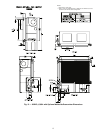
DUCT HIGH-STATIC (DHS) LIMIT SWITCH (VAV
Only) — The duct high static limit switch is a mechanical
safety that prevents duct overpressurization. The switch is lo-
cated on the side of the VAV low voltage control panel
(Fig. 18) and is factory set at 3 in. wg. To make an adjustment
using an accurate differential pressure gage, connect low side
and high side to gage and pressure source. Place a voltmeter
across common and normally open contacts. Rotate the adjust-
ment knob (Fig. 19) clockwise to increase pressure setting and
counterclockwise to decrease pressure setting. When the bot-
tom of the adjustment knob is approximately
1
/
8
-in. from the
switch body, the switch will trip at approximately 3 in. wg.
IMPORTANT: Use tubing that complies with local codes.
Improper location or installation of the supply duct pres-
sure tubing will result in unsatisfactory unit operation and
poor performance.
AIRFLOW
PROBE
TUBING
Fig. 16 — Duct Static Pressure Probe
(P/N 39EK20462)
a50-7138ef
WARNING
ALARM
REMOTE
LOCAL
OFF
ENTER
CLEAR
SRVC
HISTALGO
TEST
ALRM
3
6
9
1
2
4
5
7
8
0
.
–
STAT
SET
SCHD
EXPN
EDIT
WARNING
ALARM
REMOTE
LOCAL
OFF
ENTER
CLEAR
SRVC
HIST ALGO
TEST
ALRM
3
6
9
1
2
4
5
7
8
0
.
–
STAT
SET
SCHD
EXPN
EDIT
DUCT STATIC
PRESSURE
PROBE
BULKHEAD
FITTING
Fig. 17 — Display Panel Location on Unit Front Panel
a50-7267ef