


47
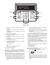
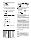
DISPLAY ALARM HISTORY — If the controller is indicat-
ing there are alarms, the user can view the alarm history by
pressing the button. The LID display will show “Alarm
History.” Press . The LID display will show the date
and type of alarm.
As an example, if the LID display shows:
ALARM — 10:55 02-11-04
SFS
That display indicates that on 02-11-04 at 10:55 a.m. the
supply fan was either on when it had not been commanded on
or was off when it was commanded on.
The user can view other stored alarms by pressing the up and
down arrows. The twenty-four most recent alarms are stored.
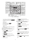
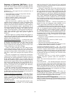
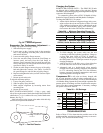
CONFIGURE CUSTOM PROGRAMMING SELEC-
TIONS — To configure the custom programming selections,
perform the following procedure:
1. Press 37 . The LID display will show:
Custom Program
2. Press . The LID display will show:
2.0 Global Dictionary
OMNIZONE
3. Press . The display indicates “No Data.” Press
then press . Press again.
The LID display should now show:
Compressor Stages
2.00 (sizes 020-034)
4.00 (sizes 044-064)
4. Press 7 times. The display will show:
0 = RAT, 1 = MAT 2 = NONE
0.00
5. Press 2 then . The display will show:
0 = RAT, 1 = MAT 2 = NONE
2.00
6. If RAS is installed at EWT input, press
3 times.
The display will show:
EWT Reset 0 = NO, 1 = YES
0.00
7. Press 1 then . The display will now show:
EWT Reset 0 - NO, 1 = YES
1.00
8. Use the down and up arrows to select the other configura-
tion parameters as required. See Table 24 for a list of con-
figuration parameters.
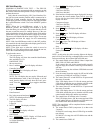
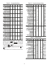
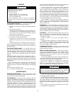
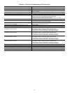
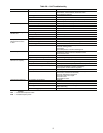
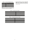
Table 24 — Configuration Parameters
*Not used.
SET CONTROLLER ADDRESS — To set the address of the
Omnizone™ system control panel controller, perform the fol-
lowing procedure:
1. Press 7 and then . Press and then
.
2. Type in the CCN element number and press .
3. Press the button. Type in the CCN bus number and
press .
LOG OFF FROM CONTROLLER — To log off from the
OMNIZONE system control panel controller Press 3 and then
. The controller password will be displayed.
1. Press . The display should show:
Log in to Controller
Logged in
If this is not displayed, Press until it is dis-
played.
2. Press the button. The LID display will show:
Log out of Controller
Press 1. Press to log off.
Sequence of Operation (CV Only) — The follow-
ing sequence applies to constant volume units only.
Cooling is initiated when the set point in the remote thermo-
stat is not met (space temperature is higher than set point). The
unit sequence of operation is as follows:
The 50BV units can be remotely authorized to be controlled
by the thermostat through the optional energy management
system relay (EMS). The coil is powered by the energy man-
agement (building automation) system whose contacts are in
series with the ‘R’ 24-v ac terminal with potential across ‘C’
(transformer common). With this terminal open, power will be
interrupted to the thermostat. Closure of this contact will allow
the 50BV unit to operate from the thermostat.
Contact closure at the ‘G’ terminal will provide power to
the supply fan contactor, energizing the supply fan. The supply
fan will be off during unoccupied schedule, depending upon
the features of the thermostat used. The ‘O’ terminal energizes
the reversing valve (heat pump units only). Typically ‘Y1’ will
also be energized at this time for cooling operation. During the
second stage of cooling, ‘Y2’ will be initialized after a mini-
mum run time and after there is a differential from set point
plus a deadband or a proportional plus integral calculation,
which is based upon demand and the length of time space-
temperature is greater than set point. Additional assurance is
provided by a delay on make timer in the second stage com-
pressor contactor circuit to avoid dual compressor in-rush start-
ing current.
For 4 compressor units, a call for the first stage of cooling
will turn on compressors 1 and 2. The second stage of cooling
will turn on compressors 3 and 4.
Heating mode (heat pump models only) follows the same
sequence as above except that the reversing valve is not
energized.
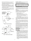
WATER ECONOMIZER COOLING — The unit diverts
condenser inlet waterflow through an optional economizer coil
to precool evaporator entering airflow. If the entering water
temperature is colder than the setting on the aquastat, and the
return-air temperature is warmer than the setting on the return-
air thermostat, the 3-way diverting valve will direct water to
the economizer coil.
Economizer water flow is in series with the condensers
allowing compressor operation while the economizer is
operating.
DESCRIPTION VALUE UNITS NAME
Compressor Stages 2.00 NUM_CMP
Reset Ratio 3.00 dF RSET_RTO
CDWF 0=NO,1=YES 0.00 CDFW_SWT
*ECON 0=NO,1=YES 0.00 EWT_SNS
EWT Reset 0=NO,1=YES 0.00 EWT_RST
*MOD.VLV 0=NO,1=YES 0.00 MOD_ECON
*0=CONST.,1=VARIABLE 0.00 FLOW_TYP
0=RAT,1=MAT 2=NONE 2.00 MARA_SNS
PHASE 0=NO,1=YES 0.00 PHAS_SWT
*FREEZ 0=NO,1=YES 0.00 FREZ_SWT
*ENABLE ECON. 68.00 dF ECON_SET
SPT 0=NO,1=YES 0.00 SPT_SNS
PRES 0=NO,1=YES 0.00 PRES_SNS
TWR 0=NO,1=YES 0.00 TWR_SNS
LWT 0=NO,1=YES 0.00 LWT_SNS
IAQ 0=NO,1=YES 0.00 IAQ_SNS
IRH 0=NO,1=YES 0.00 IRH_SNS
BSP 0=NO,1=YES 0.00 BSP_SNS
BSP Range 1.00 in. H2O BSP_RNG
BSP LOW VALUE –0.50 in. H2O BSP_LOW
HIST
ENTER
ALGO
ENTER
ENTER
CLEAR
EXPN/EDIT ENTER
ENTER
ENTER
SRVC ENTER
EXPN/EDIT
ENTER
ENTER
SET
ENTER
EXPN/EDIT
ENTER