


48
Sequence of Operation (VAV Only) — The fol-
lowing control sequence of operation for the VAV units de-
scribes the various sequences that occur depending upon the
way an operation is triggered and which software control
points are involved.
SUPPLY FAN — The supply fan can be activated in any of
the following ways:
• Unoccupied space or return air temperature demand
• Unoccupied linkage demand
• Local time schedule (TIMCLOCK software point)
• Remote occupancy (ROCC software point)
• Remote-off-local switch in the local mode
• Enabled by schedule
Once one of the above conditions exists, either TIME-
CLOCK or ROCC indicates ON or enable. The software point
OKFAN will turn on followed by the points TRMCT for air
terminal control and PUMP and TOWER to request condenser
water flow and temperature control. Approximately 20 to
30 seconds later, the supply fan (SF) point will turn ON and the
VFD output SPEED will increase. The SPEED point will
output a signal, determined by a PID (proportional integral de-
rivative loop) calculation, based on the duct static pressure
(DSP) input and the supply static pressure setpoint in
SETPT05.
Once the supply fan is running and the static pressure in-
creases above the supply fan status setpoint in SETPT01, the
supply fan status point (SFS) will indicate ON and the software
point SF_SFS will indicate TRUE.
Enabled By Unoccupied Demand
— A software point “space
control point” will display the current value of the sensor used
to determine unoccupied demand. The EWT sensor provides
this function for the 50BV unit. The display is based on the
sensors installed and the configuration of these sensors in the
custom configuration, or the status of linkage.
If there is no RAS connected to the EWT input, the space
control point will display a default value of 75 F. This value is
above the default occupied cooling set point and below the
unoccupied cooling set point. If this condition exists, supply air
reset from a sensor and unoccupied unit operation will not
occur.
If the unit is configured to use an RAS sensor for the Space
Control Point or if linkage is active and the space has unoccu-
pied demand, the software point OKFAN will turn on followed
by the software points TRMCT for air terminal control and
PUMP and TOWER to request condenser water flow and tem-
perature control. Approximately 20 to 30 seconds later the SF
point will turn ON and then the VFD output SPEED will in-
crease. If unoccupied demand is the reason the fan is on, a con-
trol force will appear next to the OKFAN point. Otherwise,
there should not be a force on that point.
If the fan is running due to unoccupied heating or cooling
demand, either the space temperature (if installed), return-air
temperature, or average linkage temperature must rise or drop
to within half way between the occupied and unoccupied set
points in order for the fan to turn back off.
Enabled by Switching to Local Mode
— When the switch is
placed in the Local mode the ROCC point will indicate enable.
If ROCC is ENABLED a software routine will override the oc-
cupancy schedule so that TIMECLOCK will also turn on.
When ROCC is turned off the TIMECLOCK point will turn
off within 60 seconds.
Supply Fan Shutdown
— If the unoccupied demand is satis-
fied and TIMECLOCK and ROCC are off and disabled,
OKFAN will turn off, SF_SFS will turn off, Tower and PUMP
will turn off, and then 5 minutes later the SF point will turn off
and the VFD speed will go to 0%.
During the 5-minute delay, the cooling and heating routines
become disabled. This delay allows a compressor that may
have just started to run for its 5-minute minimum on time with
the supply fan on. For example, if the staging routine had just
started Compressor 3 at the time the OKFAN point changed to
OFF, the cooling routine would become disabled and compres-
sors 1 and 2 would shut off right away. Compressor three
would continue to run for its minimum on time of 5 minutes.
The fan continues running until all compressors meet the mini-
mum on time and run with a load, preventing them from shut-
ting down due to a safety.
COMPRESSOR COOLING — If the fan is on and there is no
demand for heat, the Equipment mode (MODE) will be
COOL, and Cooling (COOLOK) will switch to ENABLE.
COMRES triggers the compressor staging routine that con-
trols the number of compressors energized. Units are equipped
with 2 or 4 compressors piped in separate refrigerant circuits,
and staged On/Off in a fixed sequential manner (compressor
no. 1 through compressor no. 4). The compressor control rou-
tine uses a PID calculation to determine the percentage of cool-
ing required, from 1 to 100%. Demand for the PID calculation
is determined from the supply air temperature and the supply
air setpoint (SETPT06).
Compressor cooling (COMPRES) will be turned off for any
of the following reasons:
• There is no condenser water flow (CDWF is Off).
• MODE changes to heat.
• OKFAN turns off during normal shut down.
During normal compressor operation the minimum on time
is 5 minutes and the minimum off time is 5 minutes.
WATER ECONOMIZER COOLING — The unit diverts
condenser inlet waterflow through an optional economizer coil
to precool evaporator entering airflow. If the entering water
temperature is colder than the setting on the aquastat, and the
return-air temperature is warmer than the setting on the return-
air thermostat, the three-way diverting valve will direct water
to the economizer coil.
Economizer water flow is in series with the condensers,
allowing compressor operation while the economizer is
operating.
NOTE: The return-air thermostat (RAT) is separate from the
RAS sensor.
COOLING RESET — The 5 kiloohm temperature sensor will
be used as the space control point. If this variable goes below
the occupied high set point in the HEAT/COOL MODE AND
RESET set point (SETPT03), then for each degree that the
space control point is below the set point value, the supply air
set point will be reset by the value configured in the custom
configuration RESET RATIO.
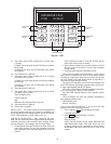
Diagnostic Features (CV Only) — The main con-
trol board (MCB) in the constant volume units has 2 LEDs that
provide diagnostic information. Refer to the Troubleshooting
section for a detailed description of the LED codes.
VAV Control and VFD Diagnostics — Refer to the
50BV,XJ Controls Operation and Troubleshooting manual for
detailed information about diagnosing and correcting control
and VFD messages.