


2
equipment. Follow all safety codes. Wear safety glasses and
work gloves.
GENERAL
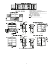
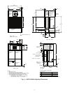
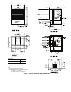
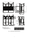
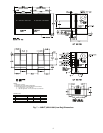
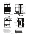
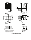
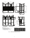
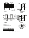
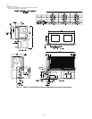
Omnizone™ 50BV indoor packaged units are very flexible
for a variety of applications. These self-contained units are
available as water-cooled or remote air-cooled air conditioning
units. The 50BV units are available with either constant vol-
ume (CV) or variable air volume (VAV) controls. In addition,
the 50BV unit is available as a water-cooled heat pump. Final-
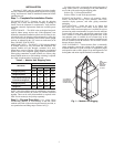
ly, Omnizone 50BV units are available in two cabinet styles.
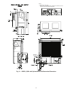
Nominal 18 through 30-ton units are constructed in a single-
piece, unpainted galvanized cabinet. Nominal 30 through
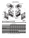
60-ton units are available as modular units, and can be taken
apart for easier installation. Modular units are built using an un-
painted, galvanized steel cabinet with steel framework, and can
be easily disassembled without breaking the refrigerant lines.
See Table 1 for a model number reference by application.
Each unit contains multiple scroll compressors piped in
separate refrigerant circuits. Each water-cooled circuit includes
a coaxial (tube-in-tube) condenser, TXV (thermostatic expan-
sion valve), individual evaporator coils, and all interconnecting
piping. Water-cooled units are shipped fully charged with
refrigerant. Remote air-cooled units are shipped with a nitrogen
holding charge.
Each unit is equipped with one or two forward-curved cen-
trifugal blowers, to ensure quiet air delivery to the conditioned
space. Constant volume units operate at a single, adjustable fan
speed and provide zone temperature control using a standard
commercial thermostat. For VAV applications, the unit is sup-
plied with a variable frequency drive(s) (VFD) that automati-
cally adjusts blower speed to maintain a constant, adjustable
duct static pressure. Compressors are automatically staged to
provide supply air temperature control (VAV applications) or
zone temperature control using a two-stage commercial ther-
mostat (CV applications).
The 50BV units have removable access panels for easy
servicing. These panels allow access to controls, compressors,
condensers, VFD(s) (if applicable), evaporator motors, blow-
ers, belts, pulleys, and refrigeration components.
MAJOR SYSTEM COMPONENTS
Constant Volume (CV) Units
MAIN CONTROL BOARD (MCB) — The main control
board for the 50BVC, E, Q, T, U, and V units provides both
controls and diagnostics including:
• Condensate Overflow Protection
prevents unit operation in
the event that the drain pan clogs (optional sensors
required).
• Random Start
provides a programmable start with a range
of 30 to 60 seconds.
• Anti-short Cycle Timer
provides a 5-minute delay to pre-
vent compressor short cycling.
• Low Pressure Bypass Timer
bypasses the low-pressure
switch for 90 seconds to avoid nuisance trips during cold
start-up.
• High Pressure Switch Delay
is a one-second delay that pre-
vents nuisance trips at start-up.
• Brownout/Surge/Power Interruption Protection
is a
20-second moving scale that works in conjunction with the
random start timer to delay unit start when a nuisance lock-
out would otherwise have occurred. This allows the water
pumps to restart and establish water flow.
• Alarm Output
contacts provide remote fault indication.
• Test/Service Pin is a jumper that reduces all time delay
settings to 6 seconds during troubleshooting or operation
verification.
• Reset
occurs after a 5-minute delay when a fault condition
occurs. When the timer expires, the unit will restart. If the
same condition occurs a second time, the unit will be locked
out.
• Lockout Reset
requires that the unit power be cycled at the
unit controller via either the thermostat or unit disconnect.
NOTE: The refrigerant circuits on dual compressor models
are completely independent. If either stage has a fault condi-
tion the remaining stage will continue to operate without
interruption. A freeze (optional sensor required) or condensate
overflow lockout will shut down both refrigerant circuits.
• LEDs
are provided for diagnostic purposes.
Variable Air Volume (VAV) Units — The 50BVJ, K,
W, and X units come equipped with a Carrier 6400 Comfort
Controller and a VFD. Refer to the 50BV,XJ Controls, Opera-
tion and Troubleshooting manual for details.
NOTE: The VAV units utilize face split coils and should not
be operated below 50% of nominal airflow to prevent coil
freezing.
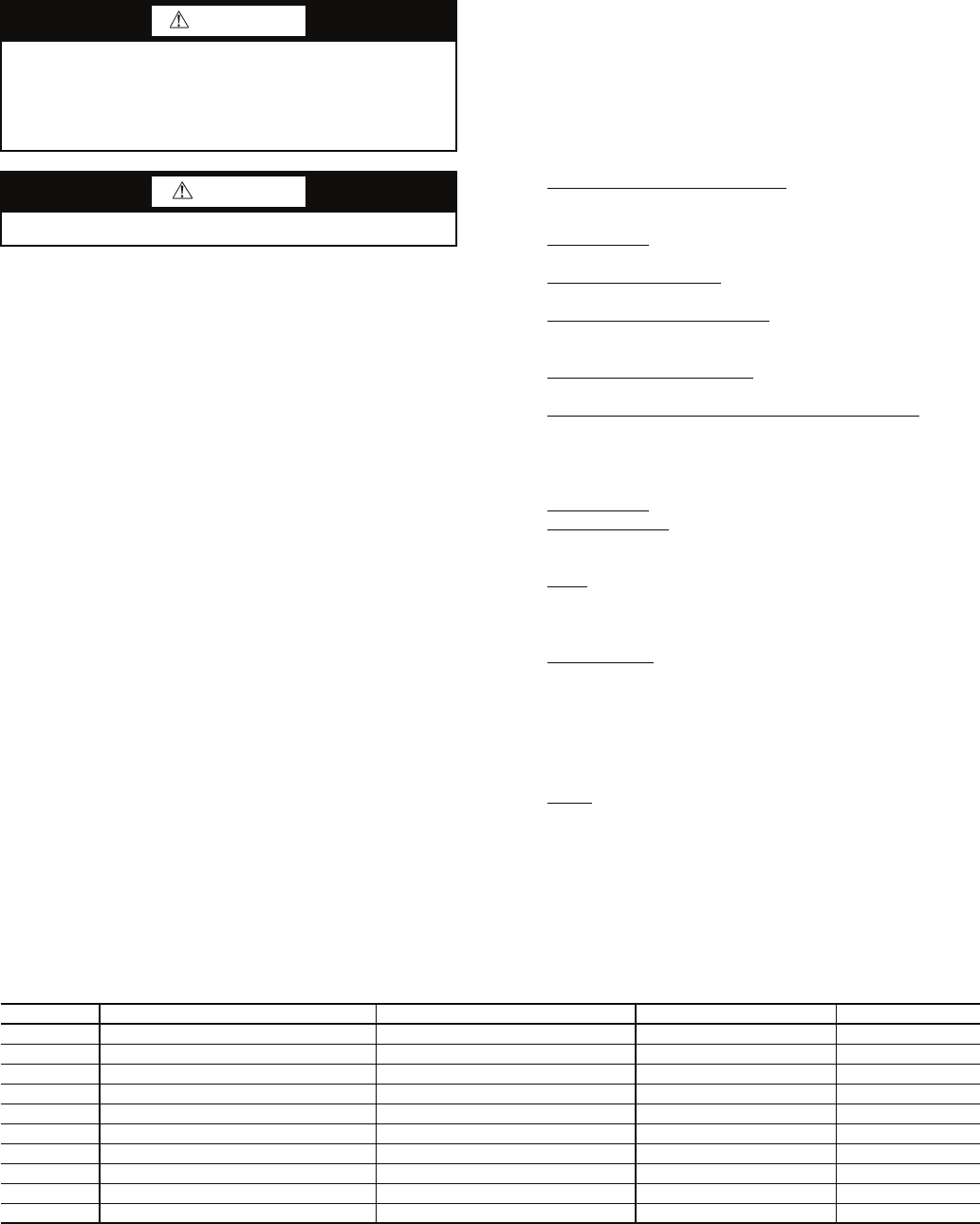
Table 1 — Model Number Reference By Application Type
LEGEND
*All units are cooling only unless specified.
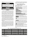
WARNING
Before performing service or maintenance operations on
unit, turn off main power switch to unit and open all dis-
connects. More than one disconnect switch may be
required to deenergize this equipment. Electric shock haz-
ard can cause injury or death.
CAUTION
Use care in handling, rigging, and setting bulky equipment.
MODEL TYPE* AVAILABLE CAPACITY CONSTRUCTION CONTROLS
50BVC Water-Cooled 18 to 30 nominal tons Single-piece CV
50BVE Remote Air-Cooled 18 to 30 nominal tons Single-piece CV
50BVQ Water-Cooled Heat Pump 18 to 30 nominal tons Single-piece CV
50BVJ Water-Cooled 18 to 30 nominal tons Single-piece VAV
50BVK Remote Air-Cooled 18 to 30 nominal tons Single-piece VAV
50BVT Water-Cooled 30 to 60 nominal tons Modular CV
50BVU Remote Air-Cooled 30 to 60 nominal tons Modular CV
50BVV Water-Cooled Heat Pump 30 to 60 nominal tons Modular CV
50BVW Water-Cooled 30 to 60 nominal tons Modular VAV
50BVX Remote Air-Cooled 30 to 60 nominal tons Modular VAV
CV — Constant Volume
VAV — Variable Air Volume